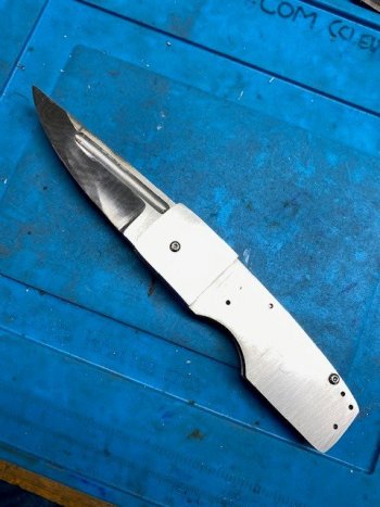
SR1 Scale Release Automatic build tutorial

I saw a post by a knifemaker recently that also engraves. I wish I could recall who it was and credit him for the reminder but here it is.

Engravers use several methods to transfer a sketch to the work piece for engraving.

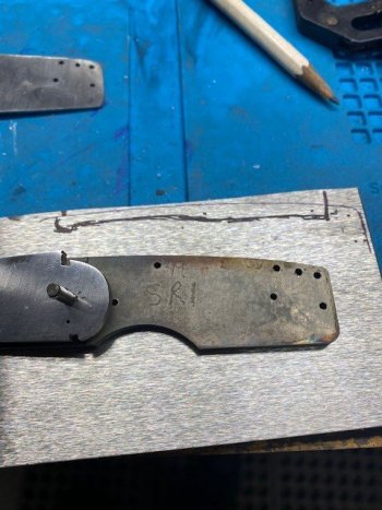
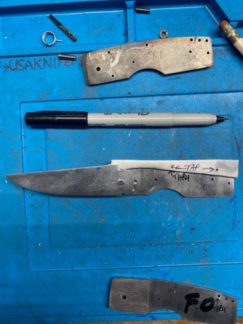
Below I have the printed out a pattern and cut out the blade and frame for transferring.

Using a clean piece of steel place your pattern, ink side down and rub it lightly with a rag soaked in acetone. The acetone wets the paper and ink and then with the mild rubbing transfers some of the ink to the steel. It is a durable transfer and this method can be used instead of gluing paper to the steel.

View attachment 76663

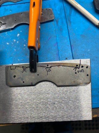
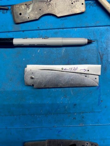
The technique is fairly easy. Hold down the paper as flat as possible and rub an acetone soaked rag or paper towel across the back wetting out the paper. It won't take much effort or time. If you rub too much it will smear. Usually one quick stroke is all that is needed. Carefully peel away the paper so it doesn't smear or wait until it is dry which takes just a few seconds.
View attachment 76664

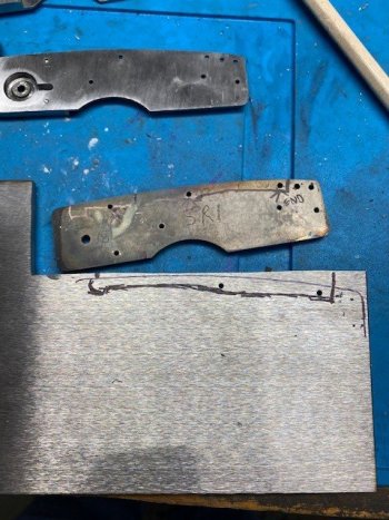
One thing to consider is the pattern will appear backwards from the paper copy. In many cases this won't matter when it is a profile and through holes.
In engraving a backwards pattern is usually a problem so it is reversed in software first and then printed out for use as a transfer.

This doesn't work with all printers but it will work with most. Set your printer to print just black as colors and color composites do not transfer as well. Some printer ink just doesn't like this method but it takes just seconds to try it. The transfer can be removed easily with a swipe of acetone.

Many printers today can scan. If you have a hand drawn sketch, scan your sketch and print the scan. You can then transfer your hand sketch printout to your steel.
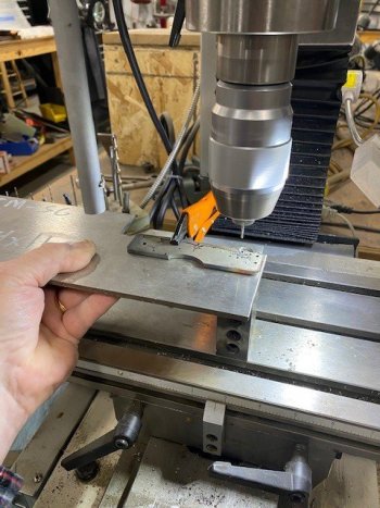
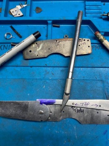
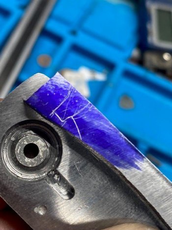
View attachment 76665
that is slick!
 
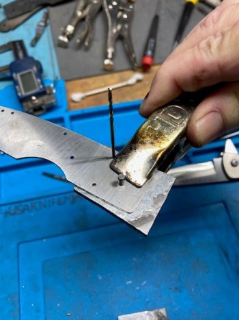
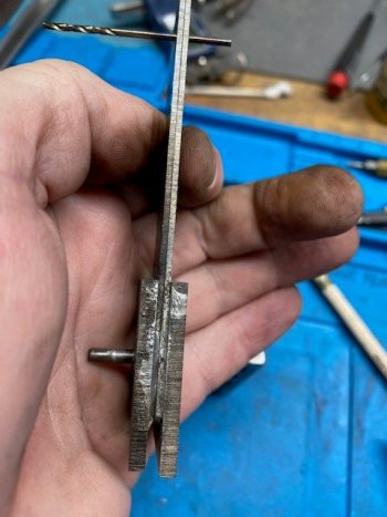
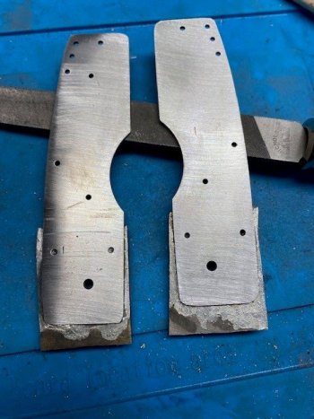
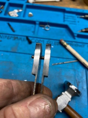
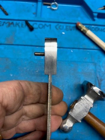
Here the bolster is aligned on the liner. The pivot pin has just a touch of oil on it to keep solder from sticking to it. The drill bit is pushed into the blind hole to get it exactly where it should be. I had to redrill the blind hole and ream the pivot hole to remove solder. Easy peasy.

Once it is clamped, I remove the drill bit or it will just fall out since the blind hole is so shallow.

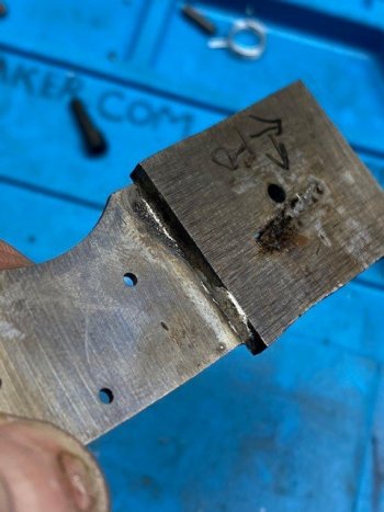
I heat the whole thing up all around with the torch. I watch for solder to ooze out around all the edges. I want a bit of squeeze out all around so I don't have any seams showing later.

The first one soldered up perfectly. I had to reflux and tin the second one again as there was a seam showing. That added just a few minutes and isn't a big deal. Mostly, it just need a bit of flux and then I scrubbed in some solder on the dry spot.

Using the blind hole to line things up is extra work. Not a lot but it's an extra step. The guys that do this all the time with slippies just eyeball it and get it done. I can't do that so I have to do a couple extra steps with the blind hole thing to get it all to line up.

aligned to solder.jpg

A little bit to clean up. I use a small file and the solder is so soft it's hard to mess up the parts.

soldered.jpgcleaned up.jpg

A quick peak on alignment before I profile the excess bolster to match the liner.
tehy match.jpg

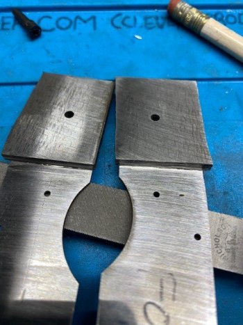
This shows how much the bolster was oversized. I do want it a bit oversized so I get solder squeeze out.
After it is all soldered, I will band saw away as close as I can to keep heat down and then I will grind the bolster flush to the liner profile.
I don't flick away excess solder like I've seen some videos do. I have had gaps show up in the seams that way. I want squeeze out all around.
Flick away excess when you are tinning but not when you are joining.

When profiling, keep the heat down. Make a short pass and dunk. Repeat.
It's easy to melt away some solder at the seam by profiling and letting the solder melt right at the seam.
both soldered.jpg

No seams showing all the way around. If there was I would redo it.
no seams.jpg

and they line up nicely. Soldering stainless is not hard but it does take a little practice. Solder flows toward heat and use only enough heat to keep it flowing.
and they line up.jpg
 
Last edited:
Ready to mill in the blade torsion coil spring pocket.
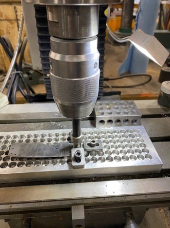
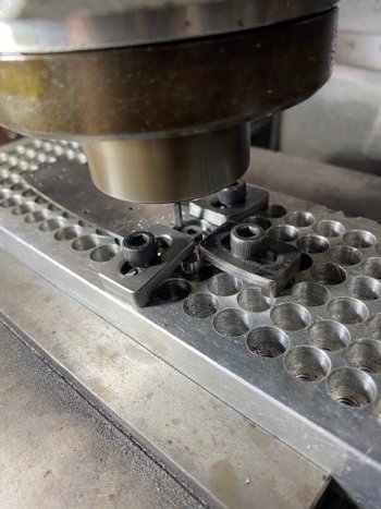
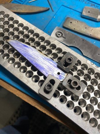
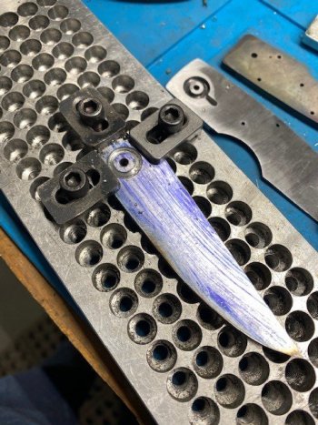
I will hold this down with a tool plate since it will be too much to hand hold in the drill press. You can make your own or https://usaknifemaker.com/knife-dogs-tool-plate.html

cutters.jpg

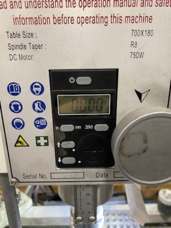
I use a Precision Mathews PM25 mini-mill. Highly recommended. It has a Z axis DRO (Z is depth or up/down). I bring the cutter down, touch it to the work and hit Zero. Now I can see how much I drill down. The coil is around .135" tall so I am going to pocket down to .120" and take some out of the blade also. The torsion coil spring https://usaknifemaker.com/torsion-springs.html )
zerod.jpg

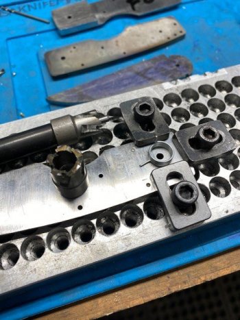
The annular cutters need to be run slow with cutting fluid. I will have to cut this twice using a 1/2" and 7/16" cutter. The coil is sized just right where the center post left by the 1/2" is too big so the 7/16" needs to be used to skinny it up. The coil will expand in diameter as it is oversprung to pre-load it and will grown in height as it is coiled. It will also get smaller in diameter as it is coiled. You have to take this into account or you will mangle springs and it just won't work right.
zero it.jpg

pocket round.jpg

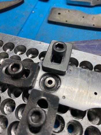
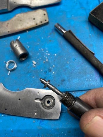
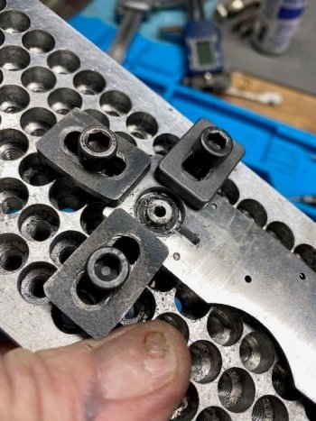
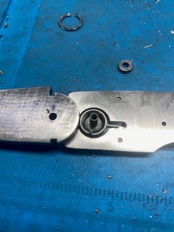
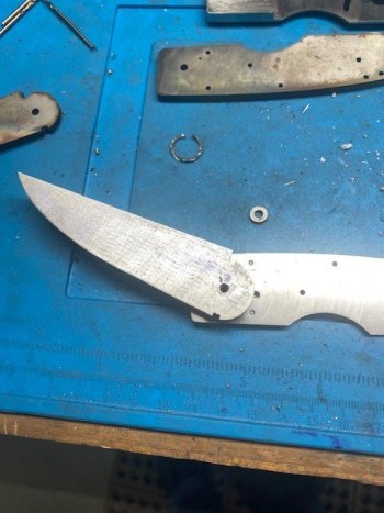
This happens pretty often I'm told. This washer looking thing on the pilot of the annular cutter is actually the liner (.050" thick) that has been cut free while using this cutter and the solder loosened. This piece is saved and used as a thick washer on the "post" side.
washer plug.jpg

I use a .125" end mill to cut out the "flag" or "wing" space for the coil spring.
mill the wing.jpg

Needs to be cleaned out but it's all cut. My depth ended up around .115". I will take the rest out of the blade.
pocket milled.jpg
 
I will add a groove to the blade to give us some additional pocket space for the coil. You could always skip this and put the entire pocket into the bolster but the knife will be thicker than it needs to be. Putting a small pocket in the blade helps keep the over all knife a little thinner. The web on this blade will still be .125"
time for the blade.jpg

blade pocket.jpg

A couple things. The thick round piece in the piece of liner that came unsoldered. It is now a washer. The wrinkled looking round piece above that was a huge burr that came out of the pocket as a result of using 2 different size annular cutters.
check the fit.jpg

Look above and see where the vertical tab of the spring is. I need to have the blade want to go to this position when the spring is uncoiled. This is a bit of pre-load so the when the blade pops open, there is still some spring tension left to carry it all the way open. In practice momentum of the blade mass carry's the blade to the open from closed position as the spring start's to loose gas about half way open. You can make a spring so strong that it will eventually destroy the knife. This blade is .150" thick and I will hollow grind it and put in some fullers to take out some of the mass or it is just going to eat it's self.

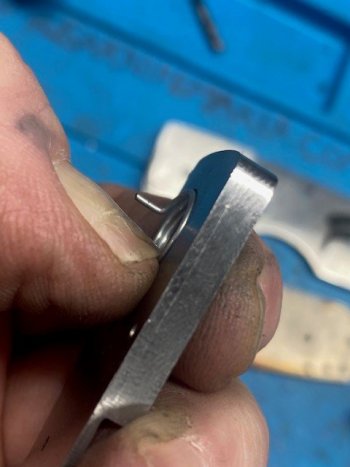
I will drill a small hole into the blade where the vertical piece sticks up. It's not hyper critical so I just guess and drill the hole in the center of the pocket groove on the blade. The vertical tab is tall enough that it will stick through the blade. I grind the tab flush to the blade.
add some preload.jpg

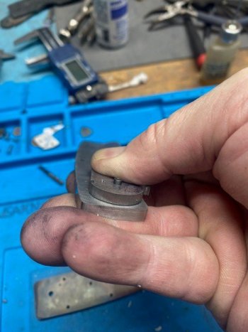
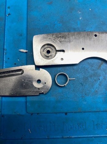
Here you can see the pocket depth on the liner. It leaves about .025" of the coil sticking out. I pocketed the blade enough to get this coil completely out of the way and to give it some room to expand.
checking depth.jpg

Here the coil is loaded and cocked and the blade is flush to the liner so we are good.
check the fit 2.jpg
 
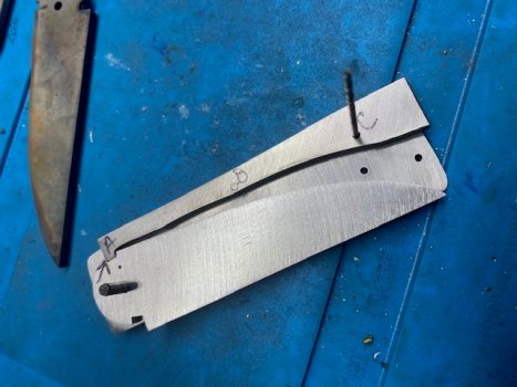
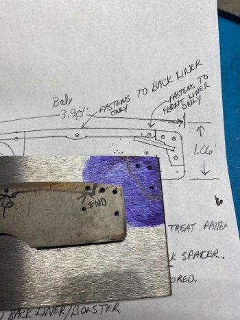
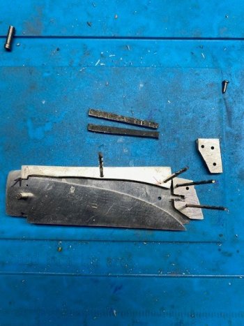
Using the pattern I have drawn up something that looks like the back bar.

spring bar.jpg

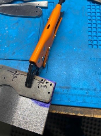
Clamp the pattern and drill it.
clamped to drill.jpg

drilling. This is with the #49 that matches this template and is the tapping size hole for a 2-56 screw.
drilling it.jpg

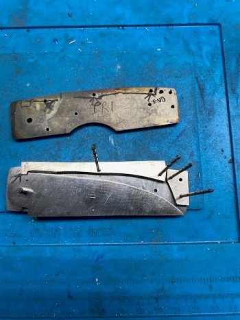
Here the holes are drilled and I draw in my cut lines generously oversized.
drilled2.jpg

The back bar is thread tapped in both holes for a 2-56. The back liner center hole is enlarged to a #44 through hole for a 2-56. The front liner also has a hole enlarged that matches the back hole in the back bar. A screw will thread through the back liner into the center hole and act as a pivot. A screw will go through the front liner and attach to the rear hole in the back bar. This is how it will pivot and lock or unlock the blade.
tap these two.jpg

closed position. I will have a fair amount to remove but it goes quick enough.
closed 2.jpg

There is two ways to do this.
1. Fit the lock on the top of the blade by hand filing and fitting. Then position everything on the liner and drill through the liner to locate the pivot hole in the back bar.
2. Drill the pivot hole (and back hole) in the back bar and then fit the lock - which is how we are doing it today. I think I should have done #1 but we will see.

You can't just fit the lock and hole it all goes together. You have to fit the lock and respect the pivot location at the same time.

I spent a few minutes filing the slot on the blade to get it squared up and where it needed to be.
I attached the back bar to the back liner.
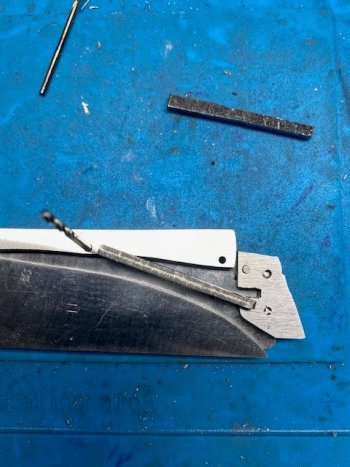
Putting the blade on top, I scribed the outline of the slot.
scribe the notch.jpg

Now I will cut and file this to fit the blade slot. Once that is done, I will not touch the bar lock lug again and will make all changes to the closed position on the blade.
scribed notch outline.jpg
 
Watch'in close... looking good!
I'm jumping the gun a bit, but do you use any kind of bearing in the knife/handle pivot point where the spring is located?
Also, to begin making one of these, are there any kinds of starter kits?
 
Watch'in close... looking good!
I'm jumping the gun a bit, but do you use any kind of bearing in the knife/handle pivot point where the spring is located?
Also, to begin making one of these, are there any kinds of starter kits?

I use a washer on one side of the blade. The back side has the vertical part of the coil spring in the way so it rides on the tang. Keep in mind there is a "post" there and not the full inside of the liner. The liner could be relieved a bit similar to what some of the slippy guys do to prevent rub on the back side blade tang.

You could also use a bearing on the front side and I have been thinking about doing that but I'll stick with a washer on this build.
Maybe.
 
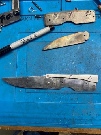
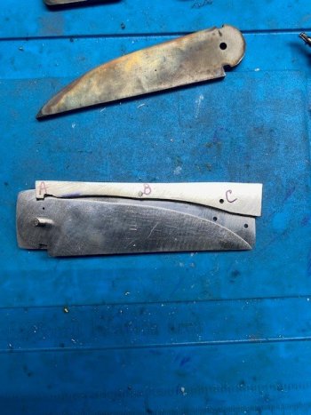
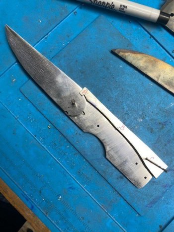
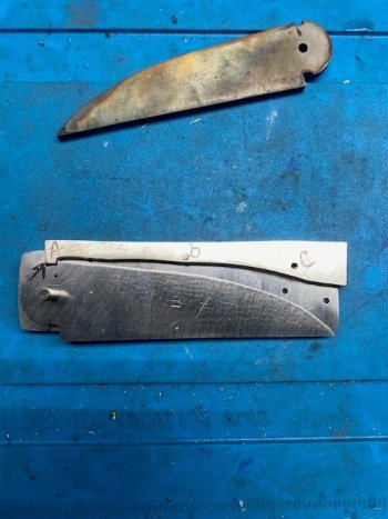
The open lock position has been filed and set.
Here the screw is holding the back bar in place so it pivots on point B.
Point A is the open position. I enlarged the blade slot big enough so that one of my files can get in there. Then I worked on the lug side to match. Once I got close, I switched to a needle file to bring it in.

It is important to note that point C has to line up with the hole or the front scale won't line up with the back one.
filing lock 1.jpg

I thinned out the back bar just bit by taking some off the blade side as it was bumping up against the blade.

Here you can see how much I have to file on the closed position. I need to relieve the back bar by Point A as it is touching there. Since the open position is done, I can only file the blade slot. If I file on the lug, the open position will move. I do want the back bar as big as I can make it as it flexes and the bigger the stiffer. Heat treating the back bar will help stiffen it a bit.
filing lock2.jpg

checking to make sure the open position lines up like it should with Hole C.
filing lock3.jpg

A hair more to go on the closed position. I need to file where the arrow is pointing.
You can look at the hole C and can probably see the hole is not quite lined up yet.
filing lock4.jpg

A little more filing and I have filed the blade slot as far as I can and still have the hole C to line up. I will have to drop the point on the blade just a hair by grinding the profile to a slow drop point. Not a big deal and I will probably like the blade shape a bit more that way anyway.

I tried this method (drill the holes in the back bar first and then fit the locks) but I will go back to fitting the open lock first, then drill holes, then fit closed position. I can still use the drill pattern to avoid using the liner as a drill pattern and wallowing out the holes in the liner.

I now have to remove the excess from Point C to the back to make room for the back spacer that holds the lock bar spring.
filing lock5.jpg
 
Time to make the back spacer.
I am using the same stock as the blade and the back bar. We haven't talked about thickness yet but the blade will need to be .010" thinner than the back bar and back spacer. The .010" will be used by a washer.

Anyway, same as the rest. Use the drill pattern we have been using all along and put some holes in the stock.
back spacer1.jpg

It should look something like this but it can be what ever it ends up too.
back spacer2.jpg

I didn't like this one as there wasn't much room for a notch to put the back bar spring.
back spacer3.jpg

So I made another one. It took about 3 minutes. I also cut a couple small strips of the 8670 that will be my back bar spring.
back spacer4.jpg

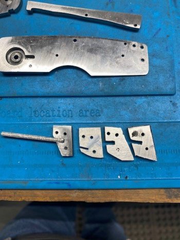
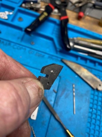
The three holes in the back spacer need to be tapped and are held in place by the back liner. That means the three corresponding holes in the back liner need to be through holes. Anyway, I went to tap the piece and I broke off the tap. I can't recall the last time I broke a tap. I was a little befuddled as I hadn't broken a tap in so long I forgot how much fun it is. There is no saving this piece so I will use it as a reference and make a 3rd one. I wanted to change the angle of the spring slot anyway.
busted tap.jpg

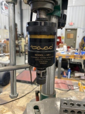
I use a tapping head and rarely (used to be never) break a tap. They wear out long before that. In this case I was hand holding the tiny little back spacer and twisted it when tapping. I will use a pliers next time.
tapping head.jpg

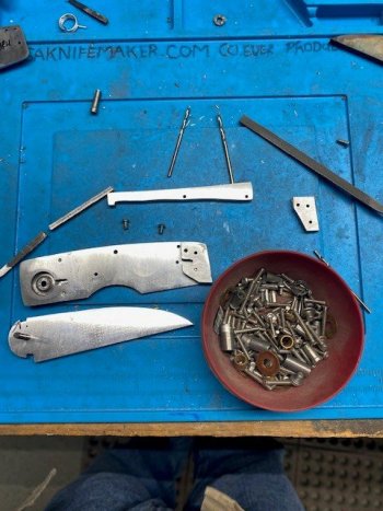
I keep a cup of mixed screws on my bench. Construction screws go in here and keep getting shorter as they are used in various folders.
screw cup.jpg

Here I managed to get two screws in the back spacer and mounted it for a peek. I will change the angle a bit on the notch but otherwise it looks like it will work.
make a new one.jpg
 
I had a couple other things going on here so this has project has had to wait on me.
I finally completed a back spacer after breaking TWO taps. The taps broke because I was hand holding these small pieces and I twisted them. I finally grabbed some vise grips to hold it and got through it. They look like PacMan guys.

lostof back spacer.jpg

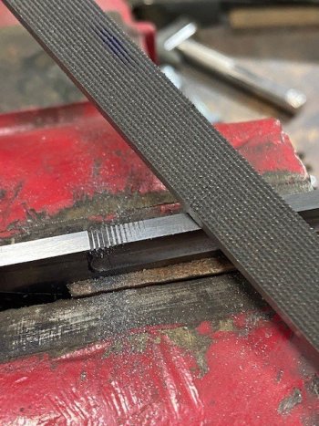
I filed some jimping on the blade. This is a 30lpi checkering file from Brownells.
It would be hard to overstate that you should practice a few times before putting this on your knife.

little jimping.jpg

I also added a fuller to the blade to help lighten it up a bit.
added a fuller.jpg

The original hole I had for the vertical "flag" on the torsion spring (6 oclock) did not provide enough pre-load on the blade.
I drilled another hole at the 3:30 position. This gave me more than enough pre-load on the blade, especially after grinding it and adding the fuller. A lighter blade is more snap. I have found a pre-load of about a 1/4 turn is more than enough. These torsion springs can only move about 3/4's of a turn before they start bending and acting up. They also move a great deal and you have to allow for that in your spring cavity.
more preload.jpg

I ground the back bar and spacer bar flush to the scales.
I did not use a rise/fall indicator to match the lock bar to the liners in both open and closed but they are not off that much. I ground the lock bar flush in the open position but could just as well have ground it in the closed position. Either way, one was going to be off a bit.

Maybe on the next one I will use the rise/fall indicator and match them.

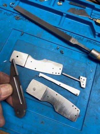
I did a rough grind on the blade and left the edge pretty thick. I will remove any other minor scratches and then give it a heat treat. At the same time I will heat treat the 8670 lock bar spring.
I also need to heat treat the back lock bar and back spacer separately as those are stainless and the blade/bar spring are carbon steel.
so far.jpg


That is all for this week. I have to take a few days to go ice fishing and also to do some engraving I have been putting off.
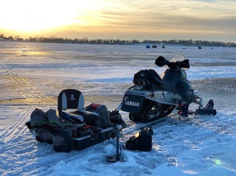
A couple years ago we moved to a lake home near Mankato. Here is my sled and portable. I can move around and pop a few holes to have a look before setting up the portable. The bite has been absolutely terrible so far this year but you know what they say about a bad day fishing.

ice fishing.jpg
 
I'm kinda lost here. My liners are only .093. Do I mill the back side spring socket into the bolster after it's soldered on? Through the liner and into the bolster

Thanks for the info.
TJ Smith
 
After it is soldered, you will mill through the liner (since it is only .093”) and into the bolster. A small “ring” of liner will probably come loose from the solder. Hold onto this to use as a washer.
 
I'm a little late to the party but if I understand this right the reason the liner moves is because it's only attached at the pivot and the back of the lockbar?
 
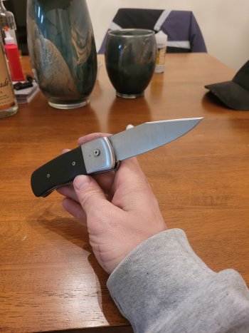
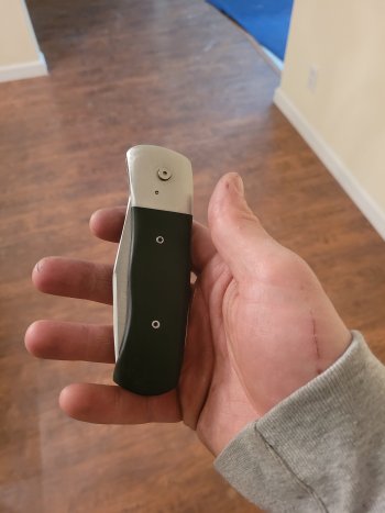
Using your tutorial I was able to complete a good functioning version of this, thank you for all the great information you put out. This was just a proto/proof of concept in AEB-L, will transition to Damascus as time permits
 
Back
Top