SR1 Scale Release Automatic build tutorial

BossDog

KnifeDogs.com & USAknifemaker.com Owner
Staff member
This post is a Placeholder for an eventual tutorial on building a scale release auto using the SR1 pattern I have released for free use.
The pattern is attached here as a file.
It will take at least a few weeks to fill in this thread. Hang in there.

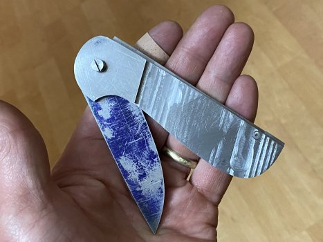
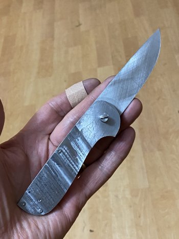
In a very simple description, these are lock back knives with a coil spring on the blade. The front liner pivots on the main blade pivot and is fastened to the back of the lock bar. The back liner is fastened to the lock bar as the pivot point. The screws holding the lock bar pivot and the back of the lock bar attach only to one liner. This allows the front scale to pivot (slightly) on the blade pivot.

The lock bar spring holds it all in place as the lock bar engages the blade in the open or closed position.

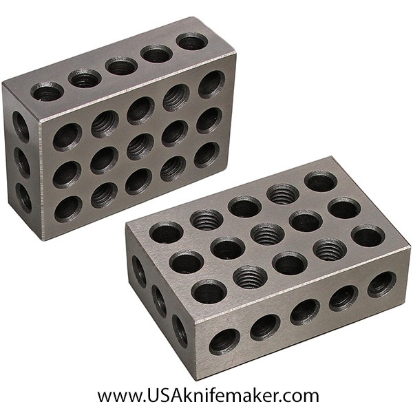
Here is a list of tools and parts we will be using. This list will be added to as we progress through the build:
Rotabroach
https://usaknifemaker.com/catalogsearch/result/?q=rotab


(These parts below are NOT used in this build but are used for traditional button release autos. I am including these here in case you are have an interest in building other types of autos.
Buttons
https://usaknifemaker.com/catalogsearch/result/?q=pp-03
Springs
https://usaknifemaker.com/compression-spring-181-x-313-x-020.html
https://usaknifemaker.com/torsion-spring.html )
 

Attachments

  • SR1 Scale Release Auto Pattern.pdf
    716.7 KB · Views: 90
Last edited:
An annular cutter is used to make the coil spring pocket. These are often referred to as spot weld cutters.
You have to measure the coil spring height and then make the pocket a little taller as the coil will expand, contract and grow taller depending on the blade position.

Rotabroach

https://usaknifemaker.com/catalogsearch/result/?q=rotab


This can be done with a drill press. Use a very slow RPM as these will go dull almost instantly if you run them too fast.

I run mine at 250RPM with plenty of cutting fluid. Here the pocket in the bolster is around .140" and the pocket in the back side of the blade is around .040" deep. These cutters hate heat. Keep them cool.

The pocket for the coil spring is milled out to hold the little horizonal part of the coil spring. I used a 1/8" end mill but a Dremel can do this also.

I have been told by two different experienced auto makers that the "flag" part of the coil is best at 3 o'clock so this is right on time.

Note the spring for the lock bar is .035" Titanium because it was handy and very easy. It is too thin so it takes and holds a bend. I will try a thicker piece and if that doesn't work I will have to modify the back spacer a bit to hold a heat treated steel spring. Working this kind of stuff out is part of the experience. Everyone will tell you a different method on hand made springs and some will work just fine. Some won't. Just know making springs is part voodoo and part rumor. Try some different methods to see what works best with your process.

I have used 8670 (which is very close to 5160) heat treated to around 55RC for a couple builds and like it. It's tough stuff.
pockets.jpg


annular cutter.jpg

There are different sizes and types of arbors. This one has a solid 1/8" pilot and will take various sizes of cutters.
11088 arbor.jpg

The cutters screw on to the arbor and it is set up for a typical 3 jaw chuck.
Some springs are just awkward enough in size you may have to use two different cutters.
On my last auto build, I used a 1/2" cutter and then followed up with a 7/16" cutter to make the pocket a little wider.

Keep in mind:
When the blade is closed the coil will get smaller in diameter and grow slightly taller. The "post" left by the cutter needs to be small enough to allow for this. The pocket depth with the blade and bolster cuts combined need to allow for the coil to get a bit taller.
You need to measure the coil and allow for the change in shape as it flexes.

The blade is pre-loaded with a small amount of tension (1/4 circumference is enough) so when it opens it still wants to go a bit further. If your pocket is just big enough for the coil to drop in, when you go to put it together you will expand the coil a bit and if there is no room to expand, it will bend and deform the coil. This probably doesn't make sense now but it will when you do your first assembly.


annular cutters.jpg
I used
 
Last edited:
Most folding knives do not have the spring pressures on it that an auto does. A liner lock has little or no pressures. A slipjoint has the back bar pressure but that is normally minimized for ease of use. An auto wants to snap open....or at least I want it to and there is usually at least two springs. As you build, keep in mind the knife is going to flex and wants to move around. Keeping tight tolerances helps. Using liner stock that is too thin will likely have you scratching your head as it flexes under pressure.

I won't go into a lot of detail about fitting the lock up on a lock back knife. There are several very good tutorials around the net on that. This pattern is not going to perfectly fit together at the lock face. You will have to hand file the blade and lock bar to fit. Fit the top of the blade first (open position). Once that is done, do not touch the lock bar face again. To fit the closed position, all the work must be done on the blade closed "slot"- just like a slip joint or lock back knife. The idea is to get the lock bar spine to line up evenly with the liners in both the open and closed position. Put your best effort into the open position fit up so there is no lock rock there. The fit up on the closed position can be a little less perfect.

Generally, the pressure on a lock bar lock face is on the blade tip side in the open position and on the tang side in the closed position as the coil spring exerts force.

You can use a rise/fall indicator like this: https://usaknifemaker.com/rise-fall-indicator-premium-knifedogs-brand-tool.html
or just do it by hand through trial and error.
 
Last edited:
Today was making a new back bar spring. I had been using a thin piece of titanium but it kept taking a bend so I had to make one from 8670.


I will grind and heat treat the blade and throw on some scales and pocket clip. I'll carry it for awhile see what the issues are.
I will also start a new one and will take and post pics/comments on the entire process.
 

This was supposed to be a pattern test build but I ended up taking it most of the way. I'll use this for my new EDC. I can tell you making and then using these with the scale release is an absolute blast. Everyone I have handed this to has not been able to open it and this is after I showed them how to. Guaranteed to make you smile when you pop it open.

There is a pattern for this in the first post.
I will be using this thread to build another showing all the steps so you can follow along.


closed sr1.jpgclosed back sr1.jpgsr1 cocked and locked.jpgsr1 opened up.jpgparts2sr1.jpg
 
This is a copy of the pattern in the first post of this thread. I printed out a couple to cut up.

paper pattern to drill pattern.jpg

I use end cuts of SS in approximately 1/8" thickness for the drill pattern. I have used .100" and that is a bit thin for this application. It doesn't matter what steel you use, SS or carbon. I just prefer SS as it doesn't rust in the shop. This stock is thick enough that a drill bit won't wander when used as a drill template. I use thin super glue to glue it on. It is an end piece of old S30v that I will never use for a knife blade.
cut and glue.jpg.

Once the patterns are glued on I slide over to my 1" thick plate I keep on my bench. I use this plate to hammer things on. I only started to use one and I wish I had one all along. It is really handy. The hammer is called a chasing hammer and is absolutely my favorite hammer. It is small, light and fits knife making chores perfectly. I think the handle shape is what sells it for me.
steel plate.jpg


I am using an optical punch from grizzly tools. It has two optical pointers and two hardened punches. One is a prick punch and the other punch is a standard. I only use the price punch. Basically you put in the acrylic optical rods and look into it to line up the marks. then you remove the acrylic rod, replace it with a punch and give it a thump. Now you have a starter hole perfectly located and punched for drilling. https://www.grizzly.com/products/grizzly-optical-punch-set/h5781
You use these only during the template build. After that you will use the drill template. Highly recommended for precise hole location to a pattern or mark.
optical punch set.jpg

After the holes are punched, I will use a center or spotting drill to slightly enlarge the prick punch holes. This allows the drill bit center and start off straight. These are usually 90degrees. I will spot drill each punch mark just slightly. Since this is the drill template it won't matter if you go a little deep here. Always spot drill your holes for folder work.
spotting drill.jpg

I keep a small cup of tapmatic tapping wax in a metal cup on my drill press. I has a rare earth magnet in the base so it doesn't slide around. When ever I drill, I run the wax onto the bit to keep it cool. Usually I dip it after every drill hole to cool the bit and be ready for the next hole. I get much cleaner holes and longer lasting drills this way.

https://usaknifemaker.com/tapmatic-edge-lube-43200-13oz-by-weight.html

I am using a123 block to lift my work off the drill table. I have about 6 of these scattered across the shop.
I also have one on my bench to use as a punch block for getting tight pins and pivots out of folder liners and frames.
The little light on the right is a gooseneck LED light from amazon called a sewing light and puts light right where you want it.

lube wax.jpg


The holes are all drilled with a #49 drill as that is the size you use for tapping a 1-72 screw which we will be using. The pivot holes in the blade and body templates will be drilled undersized and reamed to 1/8" to fit the pivot we will be using.
drilled and ready to cut.jpg

The super glue really messes up the ink from the pattern. Some printer ink doesn't run this bad but the one I used does. No worries I can still make out the outline. Some of the superglue popped loose so I reapplied some to keep the paper in place.
Next I will profile grind it all to the lines. I will grind right up to the outside line so it will be oversized by two line thicknesses - which isn't much.
rough cut.jpg
 
You've hooked me and looking forward to your next update. Wonderful descriptions & photos!
Question: What keeps the knife from opening in a pocket if pressure is applied to the side of the knife?
 
You've hooked me and looking forward to your next update. Wonderful descriptions & photos!
Question: What keeps the knife from opening in a pocket if pressure is applied to the side of the knife?
Nothing so it needs a good spring.
 
I saw a post by a knifemaker recently that also engraves. I wish I could recall who it was and credit him for the reminder but here it is.

Engravers use several methods to transfer a sketch to the work piece for engraving.

Below I have the printed out a pattern and cut out the blade and frame for transferring.

Using a clean piece of steel place your pattern, ink side down and rub it lightly with a rag soaked in acetone. The acetone wets the paper and ink and then with the mild rubbing transfers some of the ink to the steel. It is a durable transfer and this method can be used instead of gluing paper to the steel.

acetone xfer.jpg

The technique is fairly easy. Hold down the paper as flat as possible and rub an acetone soaked rag or paper towel across the back wetting out the paper. It won't take much effort or time. If you rub too much it will smear. Usually one quick stroke is all that is needed. Carefully peel away the paper so it doesn't smear or wait until it is dry which takes just a few seconds.
xfer.jpg

One thing to consider is the pattern will appear backwards from the paper copy. In many cases this won't matter when it is a profile and through holes.
In engraving a backwards pattern is usually a problem so it is reversed in software first and then printed out for use as a transfer.

This doesn't work with all printers but it will work with most. Set your printer to print just black as colors and color composites do not transfer as well. Some printer ink just doesn't like this method but it takes just seconds to try it. The transfer can be removed easily with a swipe of acetone.

Many printers today can scan. If you have a hand drawn sketch, scan your sketch and print the scan. You can then transfer your hand sketch printout to your steel.
result.jpg
 
Time to profile. I'll grind right up to the outside edge of the line.

profile it.jpg

If I have an inside arc anywhere on a design I try to make it match one of the small wheels so I can plunge it evenly. If I don't get the arc right in the design, I'll usually make a change on the fly to match a small wheel size. It just makes clean up later so much easier.
small wheel it.jpg

profiled.
profiled.jpg

The paper peeled away before I could get the notches in my blade. I just drew them in with a sharpie since this all has to get hand matched up later anyway.
notches needed.jpg

To make the notches I used the bandsaw and nibbled away.
bandsawit.jpg

I use a 20 year old HF 4x6 band saw converted to a sit down saw. If finally sprung a leak in the gear box so I'll have to take it apart, add a new gasket and fill it back up with oil and it should last several more years.
old HF bandsaw.jpg
 
Since I have accumulated a bunch of these drill patterns I've learned to scribe in the pattern name and indicate what size drills to use.
Here I am only using a #49 drill so it saved me some time by not marking all the holes. Both the blade and the frame get a pattern name so they can be matched up.

mark the parts.jpg

These are ready for heat treat. I do not make a pattern for the back spring bar or the back spacer piece. That would add additional holes to match. Any other pieces are made from these two so the holes match up exactly.

I am using type 309ss heat foil. It is rated to around 2400F. Type 321 is used for tool steels and that is rated usually around 1800.
I put a small piece of paper in the pouch to help prevent the foil from sticking/fusing to the steel. It isn't for decarb as there is barely any oxygen in the pouch to begin with.
foil timie.jpg


The first seam is simply rolled over by hand.

crease 1.jpg

Each of the seams are rolled over by hand and then hammered down flat. Run the hammer face up and down over the seam to give you a nice sharp seam. Before you hammer the seams work out as much air in the pouch as possible but don't sweat this too much.
crease 1 all 3.jpg

Then double the seam and do it again.
double folds.jpg

Into the oven.
in the oven.jpg

I probably won't get a pic of the quench since it moves so fast. I will take the hot pouch out at quench time and put it in between the plates here and close the vise. This is a cheap HF wood vise that I have mounted 1" aluminum plates to. It is fantastic for plate quenching. Put in the pouch, drop the top plate with the quick release and give the handle a half spin to squeeze it. I will then shoot compressed air in between the plate cracks. Once this is done, I'll temper the pieces twice for 60 rockwell hardness.
quench press.jpg
 
Last edited:
I keep a block of g10 on my drill press with the drills, reamers and spotting drills I tend to use. This one silly holder has saved me hours and hours of searching for drill bits and keeps mistakes down.

drill rack.jpg
 
You have me hooked. I started building one of my own design and it is coming together nicely.
But one thing I can’t get my head around is a geometry issue because theoretically this shouldn’t work (but it does). The radius of the lock bar pivot is about 1.75” and the radius of the moving scale that pivots around the blade pivot is about 3”. Because the moving scale is attached to the lock bar, the different radii should prevent it from moving. The math says the once the scale pivots down .125”, the hole should be off by 0.011”.
Since it works, I am not complaining, but puzzled why it works.
Thoughts?
 

Attachments

  • 60BC868A-3055-497C-B387-89DCB6CB5FB6.jpeg
    60BC868A-3055-497C-B387-89DCB6CB5FB6.jpeg
    1.7 MB · Views: 12
  • BC06ACE7-DB65-4A73-B16A-1F491802F9E6.jpeg
    BC06ACE7-DB65-4A73-B16A-1F491802F9E6.jpeg
    1.3 MB · Views: 10
You have me hooked. I started building one of my own design and it is coming together nicely.
But one thing I can’t get my head around is a geometry issue because theoretically this shouldn’t work (but it does). The radius of the lock bar pivot is about 1.75” and the radius of the moving scale that pivots around the blade pivot is about 3”. Because the moving scale is attached to the lock bar, the different radii should prevent it from moving. The math says the once the scale pivots down .125”, the hole should be off by 0.011”.
Since it works, I am not complaining, but puzzled why it works.
Thoughts?

First, math is a liar and I avoid it as much as possible.
Second, nice build.

The lock bar only has to function in two places and the rest of the time it just has to get out of the way. Also, the lock set in open and closed is not 180 degrees opposite on the tang. They are just arbitrary points to connect to that put the point of the blade where you want it.
 
The pattern is out of heat treat. Now it's time to select some materials.
materials.jpg

First I need to know the height and diameter of the torsion coil spring. This is called a snap gauge or snap caliper. Very handy and it is usually the first thing I grab when I need a quick measurement. Calipers are approximate but close enough for this. I would use my micrometer on more critical measurements but once you have one of these, it will be your most used measurement tool.
diameter of coil.jpg.

I always measure a few things and write them down as I will forget in 5 minutes or less otherwise.
I discovered my first mistake in the plan today. I used a #49 hole in the pattern and this is the tapping size for a 2-56 screw and not the 1-72 (which uses the #52 size) I had planned on. Just as well as I prefer 2-56 anyway.

The coil is .138" tall so I need my bolster liner stack to be thicker. The liner and bolster stack will be .182" thick so it has plenty of room to be rounded over later when finishing.

I will mill .130" in the bolster and another .020" in the blade. More on this later.

https://usaknifemaker.com/torsion-springs.html

numbers.jpg

For blade material I went and found this billet I had made last summer.
mosaic tile.jpg

It's a little thick so it has to be ripped. Cutting this on the diagonal took about 15 minutes.
cut on lateral.jpg

Here are the two slices. They should finish out around .120"
it is cut.jpg

I tried to position the blade for the best look on the billet. This will have to be ground flat. I will flatten it as much as I can on the disk grinder and then finish it on the surface grinder.
best position.jpg
 
Last edited:
The pattern is clamped to a liner side and scribed around the edge. Use blue dykem layout fluid but some guys use a sharpie or other marker.
Leave it clamped and drill through the template with the right sized drill.
the liner part.jpg

Burrs really screw things up. These burrs are really bad as the drill bit needs to be changed out. A sharp, fresh drill reduces burrs. It's important that you don't just keep drilling while these burrs are in place. They will lift the work slightly off the work rest and then your holes will not be perpendicular. I will deburr this piece several times as I drill out the pattern holes.
bad burrs.jpg

For the 1/8" pivot hole, I will put a dimple into the liner and not drill all the way through. I will then remove the pattern, drill the hole undersized and then ream to size. If you just drill through with the 1/8" drill, your hole is going to be oversized and not quite as round as it could be when reamed.
divot for the drill.jpg

I found I missed a hole and had to go back after removing the clamp and this in a nutshell is why you want a drill template. I pinned the liner to the pattern and drill out the missing hole.
missed a hole.jpg

The pivot hole is tight since it was reamed to size. I have a couple small bench blocks and a punch I have ground down to just under 3/32" to knock out tight pins. The looser your pivot, the more issues you are going to have with a solid lock up.
tight fits.jpg

The bolster pieces are cut slight oversized. Where you see the little arrow, I am going to drill a blind hole about .050" deep. I will use this as a registration hole a couple times when fitting and soldering the bolsters.
rough bolster.jpg
 
The liners and bolsters are drilled. I am pointing to the blind hole I mentioned earlier. This will be used for alignment. You could always drill these holes out for screws to the bolster also. I wanted these ones hidden. On my last build I drilled these out and later plugged the holes with a small ball bearing.

liners and bolsters.jpg


Parts get marked FO or BO for Front Out and Back Out. You would think you can just look at it and know but that isn't always the case and I've ruined -countless- parts on folders (and fixed blades) not marking things like this. The marker wears off and I will keep writing in the sides as I need to. If you aren't marking your scales and stuff and you haven't mixed them up yet, it's just a matter of time.
mark it.jpg

I stacked the bolsters and pinned them through the pivot hole. I also have a tiny, tiny pin in the blind holes to align the bolsters. I will grind the scale sides flush and check the alignment to see if it where I want. In this case, I didn't like where the scale side line ended up and went back and straightened it out.
match the bolsters.jpg

Time to solder. Soldering stainless can be a pain sometimes.
Some things to consider:
The parts should be very clean. I give them a light sanding for more tooth and then clean with alcohol. Don't touch the surface after that.
I use Stay Brite solder. The flux is called Stay Clean. It is the only solder I have found that works well with stainless. The stuff you get at the hardware store for plumbing will not work or it does, you are working much harder than you need to.

The flux will etch the surface and prep it for the solder. Heat the part slightly with your torch and apply the flux. I will put a few drops on then swirl it around with an acid brush to get even coverage. Add a little heat and you will see the flux etch in. It's really easy to over heat here. If you burn the flux dark brown, you have to clean it off and start over.

It's ok to boil it off but it's not ok to burn it brown or to chunky little crystals. Don't breath the fumes. There won't be much but still.

solder time.jpg

Here the flux has etched the bolster piece. I will take a coil of solder and heat from the bottom slowly. Once I see the first bit of solder melt I will take away the heat. Then I will use this popsicle stick to smear the solder around and break the surface tension of the liquid solder. Add a touch of heat just enough to keep the solder liquid. Some guys use a piece of wire to smear things around but I find it sucks out the heat too fast.

Once I have the work piece covered in solder where I want it, I will take it and fling the excess to the floor or scrape it off with my little stick.

For tinning like this, you only want a thin layer of solder on both parts. If it ends up too thick, take a sharp knife and peel some off.
tin the bolster.jpg

This pic is a bit out of order but when soldering the bolster to the liner, use a pencil to color inside of the liner where the bolster meets the scale. This will create a spot where the solder will not stick and saves you some clean up later.
pencil block.jpg

Here are the parts all tinned and ready to solder. I will ream out the pivot holes and re-drill the blind alignment hole.

To prep this, I will wipe off all the excess flux residue and shave flat any high spots in the solder. The bolsters are not completely covered with solder as they are oversized and the excess will be ground off.

On the liners, you can see where the solder was held back by the pencil line.
ready to pin.jpg
 
Back
Top