Press Build

3X3X3/8" is what I was thinking myself. Did you run calculations for that setup? Did you run calculations for the Coal Iron frame and find the calculations on the light side?
Seems like most of the tension is on one leg of each piece of angle-section. I think the easiest way to figure out what size members you need would be CAD. If I get bored, I might model them up in CAD and do some simulations.

Sent from my SAMSUNG-SM-G891A using Tapatalk
 
Would the tension not be shared between all 4 of the vertical angle iron sections?

That would be GREAT if you could model them in CAD. My CAD is drawing electrical control schematics, not structural.
 
Would the tension not be shared between all 4 of the vertical angle iron sections?

That would be GREAT if you could model them in CAD. My CAD is drawing electrical control schematics, not structural.
I'm certainly no CAD expert. I'll see what I can do, though. I'll post the results. I think it'll be a day or two.

Sent from my SAMSUNG-SM-G891A using Tapatalk
 
3X3X3/8" is what I was thinking myself. Did you run calculations for that setup? Did you run calculations for the Coal Iron frame and find the calculations on the light side?
Didn’t run calculations as far as strength no. I know there is a way to do it but I’m not sure the formula.
 
I'm not sure about the calculations either. Looking up specs for 1018 steel the tensile strength is around 70,000 PSI.

Tensile strength (psi)80,000 - 90,000
Yield strength (psi)70,000 - 80,000
Elongation in 2” (%)15 - 20
Reduction of area (%)50 -60

Does the above mean a 1 inch sq bar will stretch 15% each 2" of bar length at 70,000 lb of stress? I'd like to know what stress before the bar stretches more than 1/2%.
 
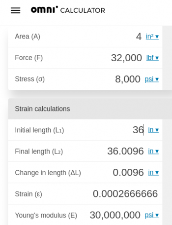
I found this webpage to calculate stess: https://www.omnicalculator.com/physics/stress#an-example-of-calculations

For the 2X2X1/4" angle frame it looks like below when pressed to 16 tons. Note the 36" frame will stretch about .01 of an inch. Not much at all. Does 16 tons look doable on that frame? Below makes the "assumption" the load will be shared equally between all 4 of the angle iron sections.

Are those numbers relative to the stress on a press?
1630518486323.png
 
The main force to contend with aught to be tension. I think the complications come in when you consider the that all of the stress is being transferred through the welds. That's what I'll try to approximate in the CAD model. Figuring 60 Ksi tensile strength for the welds. I'll make all of the steel structure 1018 CRS. I might try A36 HRS, too. If I make one, I'd be using 3"X3-1/2"X3/8" A36 angle - I got a whole bunch of it from a homeowner who's house I redid the (everything) on.

Sent from my SAMSUNG-SM-G891A using Tapatalk
 
3"X3-1/2"X3/8"? is that sorta an odd size? Is that 1/2" on one side, and 3/8" on other side of angle. With that oh hand for sure that's what I'd be using.

I think you're right on the "weak" spot could well be the welds rather than the structural angle itself. Want to make sure everything is welded really good with deep penetration.

Yes, tension for sure. My understanding the calculations above are for tension on the side structural angle iron. Of course the beam tying all that together top and bottom have to be strong.
3/8" thick, with one leg thats 3" and one thats 3.5". I think it was intended for trusses in big buildings.

By the way, I have two simulations running right now. Just waiting on them to finish.


Sent from my SAMSUNG-SM-G891A using Tapatalk
 
Assuming the pin bore at the top as a fixed point and an 32,000 pound force on the lower cross member. This is with 2x2x0.25" 1018 angle iron
ef0d1a6f9a9fab9a48f2cb29437c8f17.jpg


Woah that looks pixelated... weird. Looks NOTHING like that in person. Ill try a different monitor

Sent from my SAMSUNG-SM-G891A using Tapatalk
 
Hopefully better. Uploaded at way higher resolution, too.
6716e375c884217bdd80bfad782506b5.jpg


Odd thing is, both of those monitors are the same resolution. Just different size.


Sent from my SAMSUNG-SM-G891A using Tapatalk
 
I put the angle iron BACKWARDS. At least from how Coal Iron did it... I'll start over.........

Sent from my SAMSUNG-SM-G891A using Tapatalk
 
Thanks for doing that work. From what I can see the max stress on the structure is in the reddish color? with less stress in the yellow areas with blue area being the least amount of stress? If so, interesting it's showing less stress in top portion of frame. I'd expected the stress to be more evenly divided between top 'n bottom of frame.

I see the number .0135" as max - that the amount of stretch in the side angles plus deflection for the bottom bar? If so, not all that much difference than the .01" of the calculations shown above which are ONLY for the side angles.

Am I correct in assuming the amount of deflection shown in the CAD drawing is larger than in real? That's a LOT of deflection in graphic.

Thank you for that graphic and info.
The number is the maximum amount of deflection in the model and yes, it is VERY exaggerated. The colors on it are misleading. Because I used the pin bore at the top as the "fixed point" (it needs a fixed point), the blue area is actually deflecting pretty much the same as the red area (a bit, more be cause there's a big hole in it - I assume). So that number should (if im thinking right) represent the combined deflection of the top and bottom. The sides only pulled in a little under 10 thousands of an inch. (Edit; that number also includes stretch in the vertical members)

With either orientation of the angle iron, you have a little under a 2:1 safety factor. That's with 2X4" cross members, 2X2X1/4" angle iron and a 32000 PSI load between the pin bore and the lower die.... roughly. Depends on how wide the die is, if the work is centered, etc. I'm going to play around a little more. Look at off center loading, etc.

For what it's worth, I think air compressor tanks are tested to 300% max working pressure and lifting equipment, harnesses, etc. have a 4:1 safety factor.

I wouldn't push 16 tons through 2x2 angle iron. 3X3X3/8 aught to be more than enough.
cde90d4951b8c9f47f824588688560f2.jpg


This picture is with the angle iron oriented with the second leg on the outside of the frame. (Like Coal Iron

Sent from my SAMSUNG-SM-G891A using Tapatalk
 
Last edited:
Thank you again for your work, and please do post the results of the off center loading.
 
Thank you again for your work, and please do post the results of the off center loading.
Can do. Trying 3x3x3/8 right now.

In case you're wondering, it's pouring down rain and it's humid out so I'm hiding behind a desk instead of doing real work.

Sent from my SAMSUNG-SM-G891A using Tapatalk
 
We've had our rain for the week (about 8" or so) - what part of the world are you located in? BTW, bet there is a story behind the "52 Ford" screen name?

Have we decided the welds might not be the weakest link on the 2X2X1/4" frame since we're looking for larger angle? The 3x3x3/8 would (should?) make the welds some stronger, but not all that much? Note, that is a question, NOT a comment {g}
 
Last edited:
We've had our rain for the week (about 8" or so) - what part of the world are you located in? BTW, bet there is a story behind the "52 Ford" screen name?

Have we decided the welds might not be the weakest link on the 2X2X1/4" frame since we're looking for larger angle? The 3x3x3/8 would (should?) make the welds some stronger, but not all that much? Note, that is a question, NOT a comment {g}
Virginia, just east of Richmond. And yeah, I have a 1952 Ford F1.... I need to start working on it. Thinking I'm going to pull the body off and put it on a frame from a newer truck and restore the original drivetrain and chassis. 239 Flathead V8 and a 3 speed, VIN says it was black exterior/black interior with the "5 Star" trim package, so fancier interior trim, stuff like that. Just haven't had time to work on it. It's sitting in a barn on dry rotten bias plys right now.


The 3"X3/8" angle iron is about a 45% improvement to the "minimum safety factor" of the design. Looking at the results, the inside welds are WAY more important that the outer welds. The top, inner welds seem to take the most stress. 16000 PSI - which shouldn't be an issue, since the weld aught to have 60,000 PSI tensile strength.

Btw this picture is showing actual deformation and I don't have a tape measure on me, but it's pretty much 1:1 scale on that monitor. Looks straight to me.

One thing that i see i screwed up is I should have modeled in a pin and used that as the fixed point vs using the surface of the bore. I would expect to see a lot of force pushing up on the top half of the pin bore.... Still gives an idea of how the welds would be loaded though. I think
9326d34d7ccb5dd33917dbba6254fe75.jpg
31d0a649c886dcdbcdd969ae1b9a565a.jpg


Sent from my SAMSUNG-SM-G891A using Tapatalk
 
Old Flathead fords - I remember those in farm trucks we had. Had to rebuild them several times, but that was so many years ago and I was fairly young then. I don't remember all that much about it other than the old truck was black, had a 5 speed tranny, with two speed rear axle giving an actual 10 speeds. Never used all ten much at all. First gear was called "double low", then low, 2nd, 3rd, and high gear, then move the "dog" to high speed for highway use. Why the electric two speed axle was called "dog" I have no idea. You'll have fun with rebuilding that old Ford. It amazes me how many parts that can still be had for them. We hauled tractor and LOTS of hay bales on that old truck. I think it was a '51 Ford, and the years I remember would have been from about '59 to '65 or so.

I had mean to comment on the angle change like Coal Iron has gave a tad more deflection. Looks like the welds might not be the "weak link' I had originally thought they could be. That 15,000 psi showing on the left side, is that half of the 32,000 psi of the total? If so, that shows the load evenly divided between the two sides. Of course, that is assuming the load is centered. Looking forward to the offcenter load.

Thank you so much for modeling the frame in the program. I think we've both learned a good bit.
 
Back
Top