Help with stop pins

Stang Bladeworks

KNIFE MAKER
I am in the process of designing my first framelock. I have modified my design a bit. And im in the process of choosing all the hardware and tooling. I want to have shouldered standoffs and a shouldered stop pin to help with lateral rigidity. I also plan to use a hinderer style stabilizer. All the counterboring seems simple for the bearings and pivot. Drill and ream to the pivot size then use a pilot counterbore to set the depth. My issue is when a pilot is not available. I want to use hardened solid stop pins. I see some people have tiny holes visible on the outside of their knives for the stop pins. I assume that those pin holes are from waterjet used to locate the placment. I am wondering how they are drilled to size for the stop pin. I cant find any counterbores that small. Do you use a twist drill then bore down? Im all ears. Any tips or methods are greatly appreciated. Similarly I have the same issue when I look for tooling to shoulder the stop pins. I hope my question is clear enough. Basically how do you shoulder your stop pins and standoffs when no pilot counterbore is available?
Thanks.
 
Most frame lock guys are using CNC with an end mill for what you are planning.
They use a smaller diameter end mill and interpolate the hole to depth.

A center cutting end mill can plunge drill but setting it up to do it manually is awkward and the end mill will wander in the hole when used as a drill.

You can spot your hole, manually drill it and then follow up with that diameter end mill to "drill" to depth and get the bottom of the hole flat. You don't need to have a flat bottom hole if your frame is thick enough and the shoulders on your stand off's are small enough. The problem is the hole tends to get wallowed out into 3 or 5 lobes and then your pin is loose. The deeper the hole, the less this is a problem.

most NON-CNC guys will have parts waterjet with locating holes and then do the drilling/reaming manually. Call Chris Dunn at Topdunn waterjet. Tell him I sent you. I talked to Chris at Blade and he is ready to go. I will be using him myself on future projects. No waterjet guy will be interested in doing just a couple parts. There is too much time involved in set up. I don't know what his minimums are. My advice is to build a couple models manually and refine them before you send off your first drawing to have a run of parts cut if you plan to scale up. If you are just doing the occasional "one off", don't waterjet.

If you are going to use shouldered stand off's/stop pins, your blade thickness and washers (or bearing stack up) has to be dead on thickness. It's not trivial to get everything to exact size finished. A thou is a mile in quality folders. Spacer bars and floating stop pins are significantly easier.

If you are going to do a run and sell them, you might want to look at paying the license to Hinderer for the over travel thing. It's not that much. I don't see him caring much about a guy putting out the occasional custom with out the license.

The other option is to have some custom carbide counterbores made. It's expensive. I have them made for corbys and folder parts routinely and have to buy 25 to 50 at a time to get anything done.
 
Great info there Tracey - can you explain what a “floating stop pin” is please? I’m only making small numbers and one offs and I don’t have a mill but I have a hunch that the way I do my stop pins are probably what you are referring to.
 
Most frame lock guys are using CNC with an end mill for what you are planning.
They use a smaller diameter end mill and interpolate the hole to depth.

A center cutting end mill can plunge drill but setting it up to do it manually is awkward and the end mill will wander in the hole when used as a drill.

You can spot your hole, manually drill it and then follow up with that diameter end mill to "drill" to depth and get the bottom of the hole flat. You don't need to have a flat bottom hole if your frame is thick enough and the shoulders on your stand off's are small enough. The problem is the hole tends to get wallowed out into 3 or 5 lobes and then your pin is loose. The deeper the hole, the less this is a problem.

most NON-CNC guys will have parts waterjet with locating holes and then do the drilling/reaming manually. Call Chris Dunn at Topdunn waterjet. Tell him I sent you. I talked to Chris at Blade and he is ready to go. I will be using him myself on future projects. No waterjet guy will be interested in doing just a couple parts. There is too much time involved in set up. I don't know what his minimums are. My advice is to build a couple models manually and refine them before you send off your first drawing to have a run of parts cut if you plan to scale up. If you are just doing the occasional "one off", don't waterjet.

If you are going to use shouldered stand off's/stop pins, your blade thickness and washers (or bearing stack up) has to be dead on thickness. It's not trivial to get everything to exact size finished. A thou is a mile in quality folders. Spacer bars and floating stop pins are significantly easier.

If you are going to do a run and sell them, you might want to look at paying the license to Hinderer for the over travel thing. It's not that much. I don't see him caring much about a guy putting out the occasional custom with out the license.

The other option is to have some custom carbide counterbores made. It's expensive. I have them made for corbys and folder parts routinely and have to buy 25 to 50 at a time to get anything done.
Thanks for the response,

I have used a local waterjet company in the past. So far they have been accurate enough for slipjoints. I'm not sure if the accuracy will be good enough for framelocks or not. my intention was to use them at first. I love using waterjet to locate the holes as long as its accurate enough. They are a local company just down the road from my work and they will do small batches. Their policy is a $50 minimum but they have even waived that for me I the past. To get a blade and spring cut is like $5 plus they are fast. I live in Canada so shipping to the US is expensive and slow. I am very passionate about this project so I want to do the best job possible. This has been my goal since I started making knives. I want to use a stop pin that is shouldered for added lateral rigidity. I have been working a ton of OT lately to help gear up for the project. I plan to order a grizzly G0759 which is a 704 with a DRO and all the required tooling and materials in the near future. I understand this machine has its limitations but for many reasons I think it will be the best fit for me and my budget. Used machinery is rare and expensive where I live. I would rather not have the pin hole from the waterjet but I think It will be a necessary evil given the limitations of my machine. By no means do I expect this to be profitable I just want to get some repeatable processes figured out.

I am wondering if this is my intended method for both the stop pin and standoffs what method is best to accurately counterbore the holes. I need to be able to hit a precise depth so I snow exactly how short to cut my stop pin and standoffs. Can I use a twist drill or some kind of similar drill to start my hole and get the proper location and diameter established then use something to bore down and produce a flat bottom. I have been lurking on some machinist forums and I have read that end mills are not flat bottom which would make it difficult to know the exact depth because the pin can reach the bottom of the hole. I have seen on youtube some guys use a reamer but I don't quite understand how that's supposed to work. Maybe my construction method isn't feasible with my equipment but I want to try. Hopefully my question makes some sense. Its difficult to ask a question in a topic I'm not well versed in.

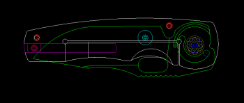
Thanks for your detailed response. I appreciate your input and that you have taken time out of your day to reply to my question. below is a pic of my design in progress. Its not done yet but I thought it may help where my terminology falls short.
69015
I'm open to any and all suggestions. Also as far as the stabilizer goes I say them for sale at ti connector and they license them. I assumed that I was covered there but it couldn't hurt to reach out to hinderer just to be sure. I'm sure he wont be too worried about me.

Thanks again.
 
Getting an exact depth will be difficult using any manual process. Most of these blind holes are approximate (talking manually here) depth and the pin or standoff is taken manually to approximate length to fit. The pin or standoff does not need to bottom out and probably shouldn't.

A reamer gets holes rounder but does not cut on the bottom.

I've talked to Steve Kelly about those and he does pay the license on those so it's covered.

Frame locks are made with a drill press and grinder all the time and it's all you need. Additional equipment makes it easier but all you really need is that.
Thanks,

Even if I need to have it as a floating stop pin at least if its shouldered it will provide some lateral rigidity. I have been tweaking my design to try to get something that is repeatable and accurate given the tooling that I have. Glad to hear about the license. I am a huge fan of the lockbar stabilizer. I appreciate your input on this. I am very excited about the idea of finally being able to make a framelock. I am aware that lots of people are able to make awesome stuff with minimal equipment. I don't know how they do it. I have a lot of respect for people who can substitute equipment for skill and patience. Sadly I am not one of those people so I will try to utilize my equipment to it fullest to account for my lack of patience. Luckily for me there are a few people like yourself who are willing to share their knowledge. Much appreciated Sir.
 
Hey there i read ur post and here is my 2cents. I use a water jet. But only for hole LOCATION . I bring all else sizing is done on old swedish mill called Modig. I drill and ream in pairs and my stop pin is a threaded sleve from steven kelly. I have reached a point and do not know how to proceed. BOLSTER i can not find anyone to give me or show me about bolsters. Note my stop pin held with screws and so are my rear standoffs. Bolsters. How to include them?????
 

Attachments

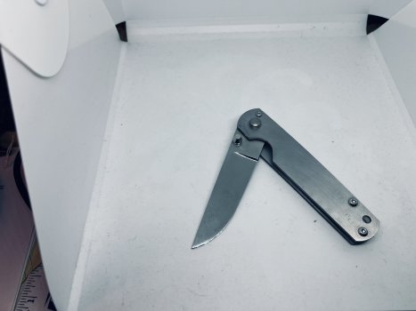
  • 98C22EB7-AB53-498A-B442-A7D626F4664A.jpeg
    98C22EB7-AB53-498A-B442-A7D626F4664A.jpeg
    385.7 KB · Views: 6
Aikenn, this thread is three years old, you should post a new thread with your question about bolsters, but the way I do it is with 0-80 screws thru the bolster into the liners. my stop pins are 3/32 hardened pins that sit flush with the liners. I use pivot pins that use 4-40 buttonhead screws. I countersink the bolsters for the buttonhead screws. I don't use standoffs, I use back spacers with 0-80 flathead screws going threw the liners.
I hope any off this helps you.
 
Back
Top