First slip joint WIP

JS,

I made 1 slippie so take this for what it is (limited experience) But I traced my tang on paper then set a compass to the shortest distance from the center of the pin to the flat of the tang then drew a complete circle around the pin.

After doing that I set my caliper to the correct distance and scribed on the tang and ground the top and rear flats down to the scribed line. Remember that in the closed position the blade will be contacting the spring on the bottom back corner of the tang and the kick so a straight line between these two points will be what falls on the circle. Once you establish the top and back of the tang shorten the kick until that sraight line is on the circle and you should be flush in all 3 positions.

Without having a dial indicator set-up to check the fit this method got me so close to flush in all three that I couldn't tell the difference.

Hope this isn't too confusing.

-Josh

This is an excellent idea and I understand it perfectly. Even if I do use an indicator fixture, this is still a very helpful suggestion for me to implement in addition to that. It's also great information for people who do not have an indicator fixture.

It took me doing a couple of them before I realized that the back corner of the blade and the kick are (in unison) what is touching in the closed position. For a little while there I thought it was only supposed to be the flat itself, with some sort of relief ground to clear the kick. When I fit the first one together - the one in this thread, that's when I saw that it was actually both of those areas in contact and that the position can easily be corrected by removing material from the kick, or both.
 
JS,

Glad you found that helpful !
As you mentioned this method I think can still be valuble even with the use of a dial fixture. One thing I probably should've mentioned is to round the back corners of the tang before adjusting the kick as rounding afterwards would surely change things and cause problems.

Josh
 
well I cut the scales tonight guys. The wife and I were looking at it aftewards and we both agreed, it's really going to look good. I did take pictures as I was doing everything, but I don't have time to go through the posting process tonight. Maybe tomorrow, if not then, definitely saturday. I've decided to try to finish this one first before I focus my attention on the other three, and they will probably be one at a time as well. I don't know if nybody else has a problem like I do with this, but it is hard for me to spread my attention over several projects. I work and do my best when I focus on one thing at a time.
 
For your first Knife of this style, You sure are doing a Great Job!!! Can't wait to see it finished!! GO BAMA!!! :)

Frank
 
I'm enjoying this immensly ! I'd like to know with is the thickness of the liners used on slip joints and where is a good spot for the the spring pivot to be , meaning a per centage of the length? Thanks Frank
 
I'm enjoying this immensly ! I'd like to know with is the thickness of the liners used on slip joints and where is a good spot for the the spring pivot to be , meaning a per centage of the length? Thanks Frank

The stuff I am using for liners is .048" thick Frank, but I think other makers use a little bit theinner stuff. Personally I wouldn't go less than .040".

Where you put your center pin could easily be debated, and I am in no means at any position to offer advice on the subject. Maybe someone with much more experience will come in.

I will tell you what I think though. I would imagine that the closer you put the center pin towards the blade, the stiffer the spring will be. If you move it back towards the rear of the handle (away from the blade) it will be more lazy and forgiving. Of course, when you heat treat and draw the spring (temper it) this will have an effect in its own on it. In other words, You might have a center pin really close to the blade but the spring is drawn way back, and on the other hand you might have a center pin further back away from the blade with a slightly tempered spring (still pretty much hard for the most part). These two springs would feel very similar, if you get my drift.

I would think that setting the pin further back away from the blade would be the safer choice though, because the closer it is to the blade the more stress it has. I would imagine this would make it more likely to break over the life of the knife. Probably a safer bet to set it back further towards the rear.

Just my .02
 
Just wanted to let everybody know that I will be updating the thread in a day or two. I tried to get it updated over the weekend but other things got in the way. I did a little more work tonight and took some pictures but it's too late for me to go through the uploading and posting process tonight. I promise to get it done soon.

Stay tuned :)
 
Not acceptable this should be done already....insert loads and loads and loads of sarcasm lol.

Lookin good man.


laugh.gif


Working on the post now man. Should be able to get it up tonight. I also just heat treated the blade - came out 61 RC, drawing it at the moment. Also need to draw the spring. Not sure what a good hardness for this would be..
 
I started on getting the handles set up the other day, and said I would get back to this write up with pictures.

Here I have grabbed my liners with the bolsters we soldered on the other day-
slipjoint72.jpg


The first step here is to saw off the excess material around the liners. I leave a little stock so I can grind them back to the liners. Even then, I don't go all the way to the liner because I want to be able to do one final clean up sanding once I get the whole assembly together. Here we are sawing the liners bolsters and a shot of them finished -
slipjoint73.jpg


slipjoint74.jpg


Time to clean them up really good. The soldering flux makes a mess. I made sure to get the solder out of the little area where the bolster meets the liner so that our scales could fit flush. I used a dental pick looking sribe I have to do this. I have no idea where this tool came from, I just found it in an old box somewhere years ago. It works great for this -
slipjoint75.jpg


I took a file and finished cleaning up the stray solder and then put the pieces on a small fiber deburring wheel. These work really good for cleaning -
slipjoint76.jpg


slipjoint80.jpg


I then rounded and shaped the bolsters to something close to what they will be when finished -
slipjoint77.jpg


You need to be sure both sides are pretty much the same. here are some finished roughed in shots -
slipjoint78.jpg


slipjoint79.jpg


I laid out the pieces of Stag that I got from Tracey Mickley and cut them a bit oversize. You want to be sure and cut oversize here so that way you are sure to have enough material to work with. Here are the scales before cutting and after. This is my first use of this stag material, and I thought it would be much softer than it really is. It is actually pretty hard and dense stuff -
slipjoint81.jpg


slipjoint82.jpg


These scale pieces are close to 3/8" thick in some places, and that is way too much for what we will use here. I will have to cut the back of them down with a rough belt to get the scales down to a little more than 1/8". The dashed red line is where we want to be and the red x is what has to be removed.
slipjoint84.jpg


So we sand on the backs of them, all while taking every precaution to not let or fingers slip and create a very painful reminder of why we need to be careful-
slipjoint85.jpg


Fitting the scale pieces inside the bolsters was a little tricky, but just take your time. My advice is to start with one flat side. I started with the pivot pin bolster because it is more straight than the other tail end bolster - which is angled. Once I establish that first flat with the disc grinder, I can work from that flat. Take a little off of each side slowly until you work it down to where you can see that you have it close. I would leave about 1/8" on top and bottom. You can clean this up after you pin the scales to the liners. Creating the first flat to work from -
slipjoint83.jpg


After I got my thickness, I put the scales on the disc sander and trued the back of them a little better. The disc seems to be pretty flat and creates good results; the belt doesn't do as well. Again, be careful here and watch your fingers. Grinding disc / belt sander wounds really suck because they are a mix between a burn, a wound, cussing, and pain-
slipjoint86.jpg


And the finished thickness -
slipjoint87.jpg
 
I also forgot to add that this stuff stinks like something awful when you work it. I had to wear a mask. My wife told me last night..No more stag in the house :)
 
I just got the spring out of draw. It was 61RC too as it was heat treated with the blade. I put it in draw at 900 degrees hoping to pull it back to about 50RC, but it came out at 55RC. I put it in this morning for 2 hours at 1100, and it pulled it all the way back to 40RC :(

Went too much temp on second draw I guess. I'll re heat treat it as soon as the oven is availabale again.
 
Today I did some fitting and got the scales into the liners between the bolsters. I aslo drilled the holes for all the pins.

A trick to doing the final fit on the side of the scale against the tail bolster is to turn it over like this and draw a line from one edge of the bolster to the other edge. Or, mark the scale where the bolster is on both sides and the connect the line. Don't try to get this dead on because if you do it will bite you. I didn't do it, but I bet you it will come up short if you don't leave some stock on the scale to work with -
slipjoint88.jpg


Marking the line with a straight edge (something straight) to connect the two marks -
slipjoint89.jpg


Once you have this angle correct (the one you created with the line you marked and connected) you can take a little material off at a time, until it fits down in between the bolsters. Slide the scale down into the liner from the top like this, and check your fit at both ends as you work -
slipjoint90.jpg


The reason I left a good bit of material on the top and bottom of the scales is so that there will be something to work with in those places after this step. If the angles are right and there is stock on top and bottom to work with you're in shape -
slipjoint91.jpg


Here is a pic from the back; You can see the extra material on top and bottom-
slipjoint92.jpg


After you have gotten this far, take your pencil and draw lines to represent where the scales need to be trimmed to. Be SURE you have the scales where you want and be careful not to accidently move tem while you are tracing. After you get through you have clear defined lines for trimming excess material -
slipjoint93.jpg


v\
slipjoint94.jpg


To drill the one hole for the center 3/32 pin and the two holes for the 1/16" scale pins, place the scale inside the liner and secure it with clamps or something to hold it steady. Turn the liner with scale inserted upside down and clamp this to a parallel of some sort with a hole in it. If you want to clamp the hole assembly as one (scales, liner, and parallel) that is ok too, just be sure you have room to drill your holes. You will most likely have to move the whole set up three seperate times for each individual hole. All this is supported on some 123 blocks or other parallel pieces of material. I got this trick from Bruce Bump's tutorial and I have to say it is an awesome idea. I was blown away when I saw this setup in his thread because this is probably the best way I have seen to maintain the squareness and plumb of the holes, especially if you have some odd shaped handle material with no flat like this stag. Here is his picture from his thread -

100_7523_edited.jpg


And here is mine. I have my 123 blocks here and I made the little parallel piece with a hole in it. It's just ground stock with a hole for the drill to pass through-
slipjoint95.jpg


And drilling the holes for the scales in the setup -
slipjoint97.jpg


After I did the center hole / spring pin hole in each scale, I had to drill the 1/16" holes for the smaller pins on each end. I laid the liner/bolster assembly on the drill press table and just eyed these in. Just as long as they aren't way over in left field..I was still able to do this because my bolsters still have flats. I haven't completely rounded them off yet, and that left a stable flat surface for this operation. You want to do the same thing with the parallel here too when you transfer the holes in to the stag as we did with the spring center pin hole, to be sure they are true and straight -
slipjoint96.jpg


Now that you have the holes drilled and the scales on the liners, you can finish cleaning up the scales so that they will be even with the liners. You can leave this and finish it later too if you would like. I took mine down to just a hair above the liners, so that I can do that final sanding I was talking about. Here are some pictures with the scales on. It is starting to look like a cutting tool aint it :) -
slipjoint99.jpg


slipjoint100.jpg


And for Ernie, a picture of the blade after heat treat -

slipjoint98.jpg


Next post we will attempt to put the shield cut in the liner. I still have to make the shield itself. I chose not to use a bushing in the blade, so no attention has to be reserved for that.

Stay tuned.
 
Last edited:
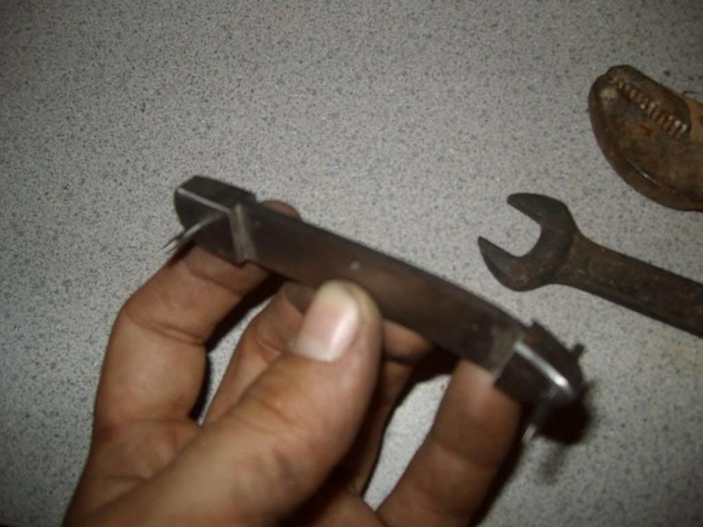
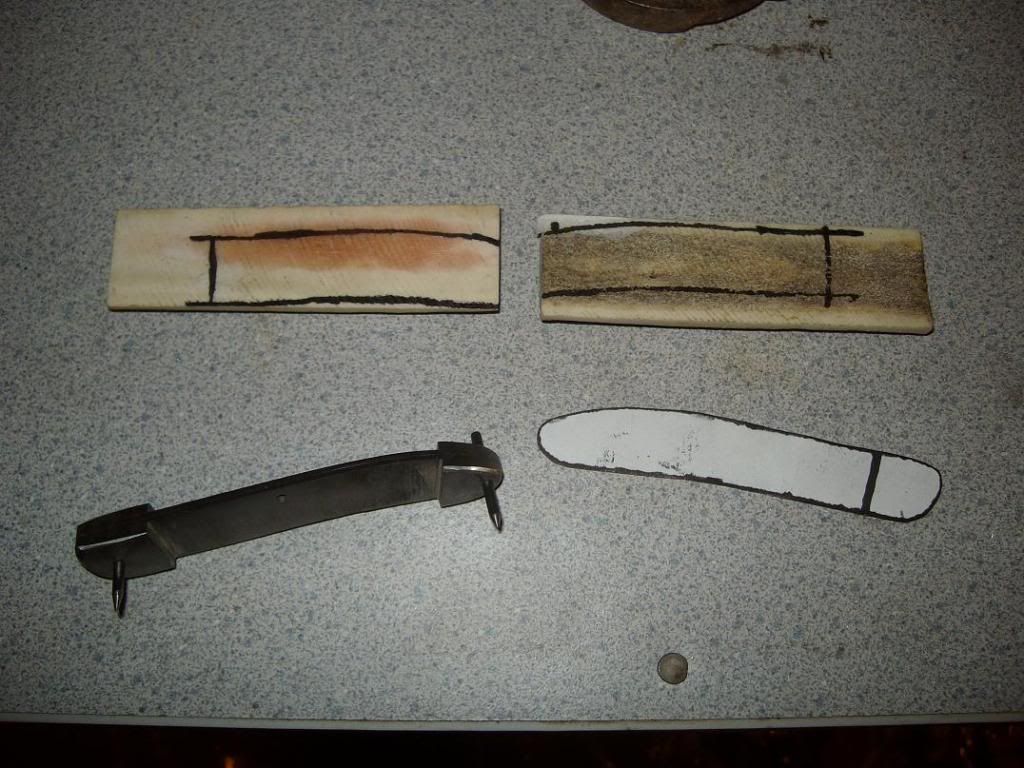
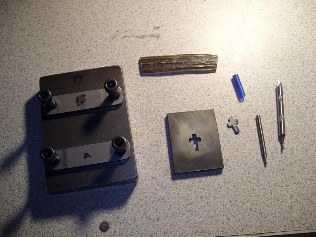
Ok guys, a day off of work today and I got alot done. I started to put the shield in the liner and realized I had forgotten to make a fixture to hold the liner while it is being cut. I got the idea from Bruce Brump's thread and built one similar to that. So, once I got that done I laid everything out to get ready and do it. Here we have the liner, the negative plate, the shield, two 1/16" endmills and the fixture. If you look really close, you can see that one of the endmills is double end, and one end has been broken off. That's what happens when the speeds and feeds figures you use are a little fast in a cnc.-
slipjoint101.jpg


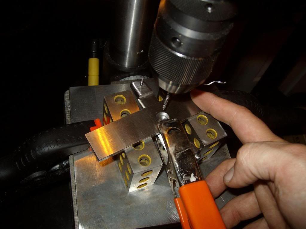
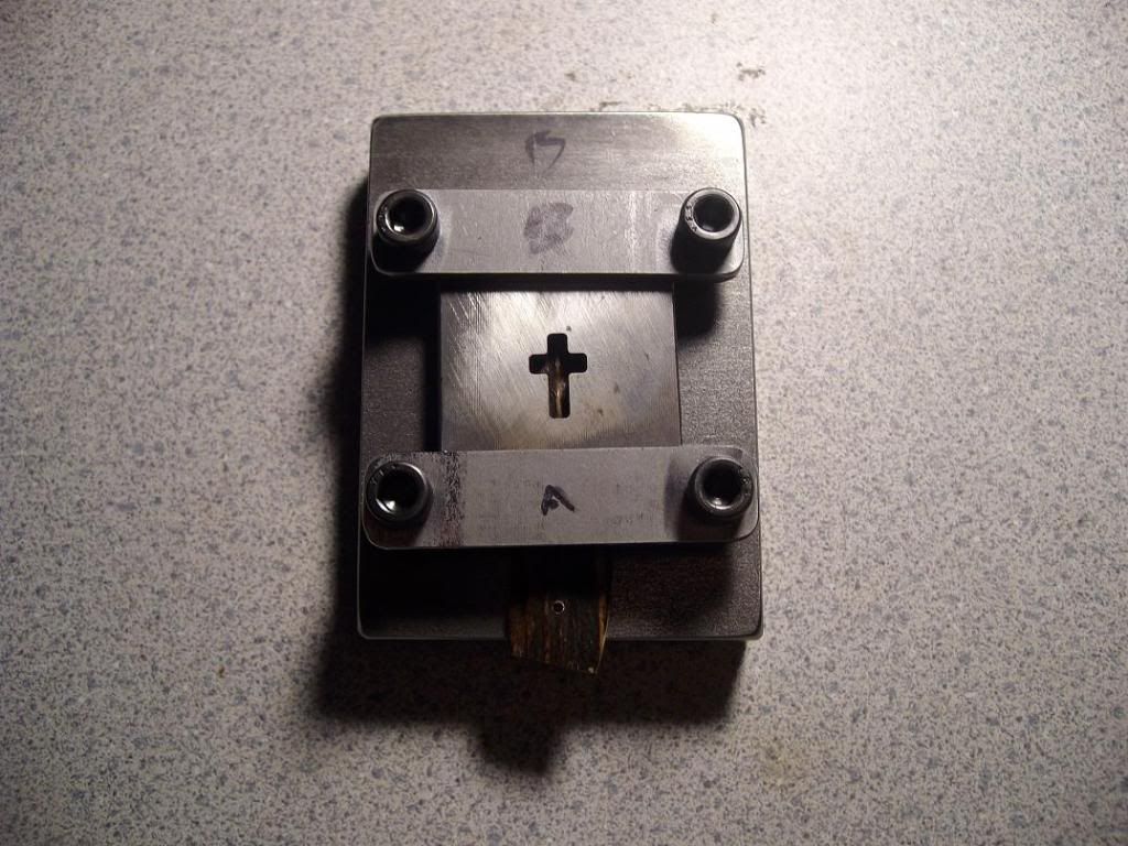
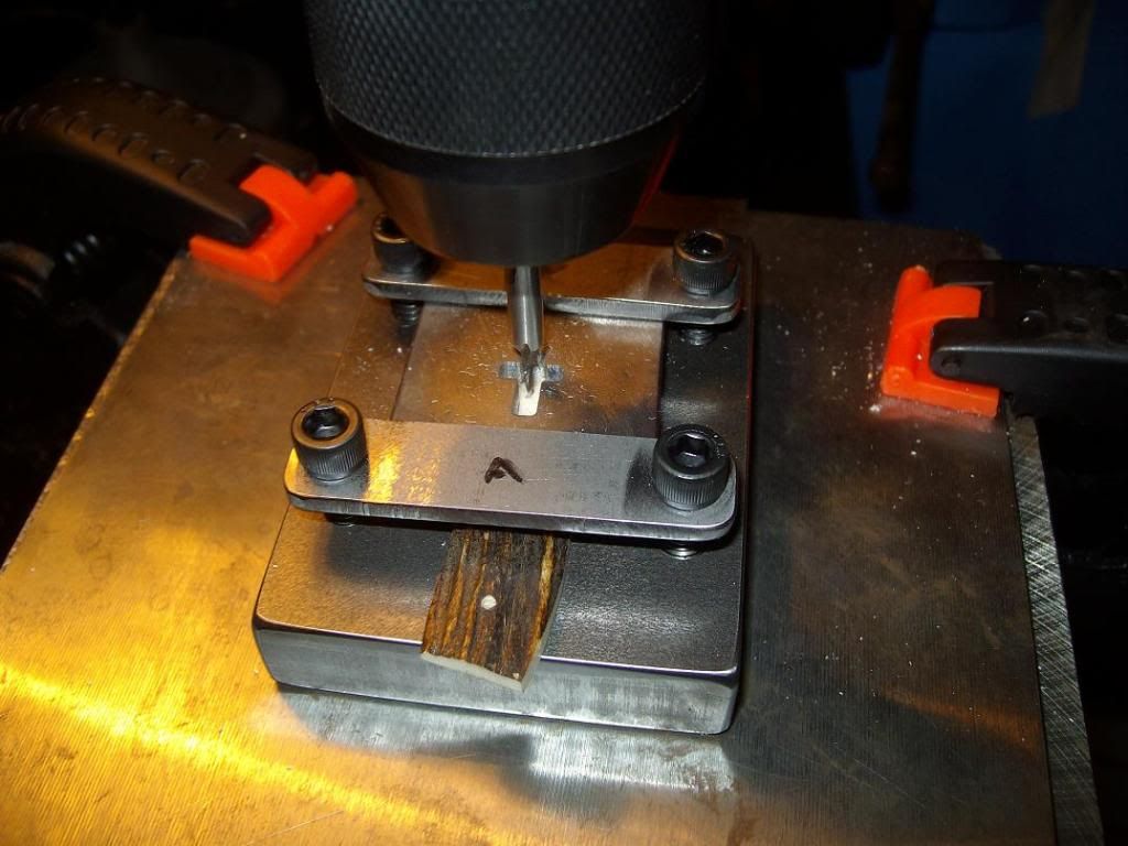
Here it is bolted in. Be careful not to tighen the bolts too tight. This stag material seems pretty forgiving, but I'm sure that there are some handle materials that may be a little brittle. I can't imagine doing this with mother of pearl or something like that. Here we are ready to cut-
slipjoint102.jpg


Spin the endmill as fast as you can go. An endmill this small needs to be spinning really fast and you don't need alot of pressure to cut- Slow and easy. soft material will cut fine, so you don't need to be in any hurry. Here we are cutting-
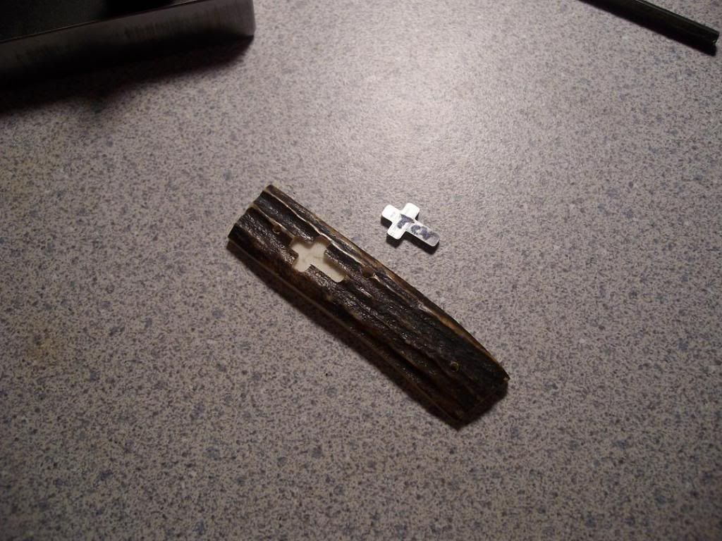
slipjoint103.jpg


And finished-
slipjoint104.jpg


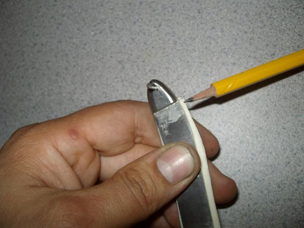
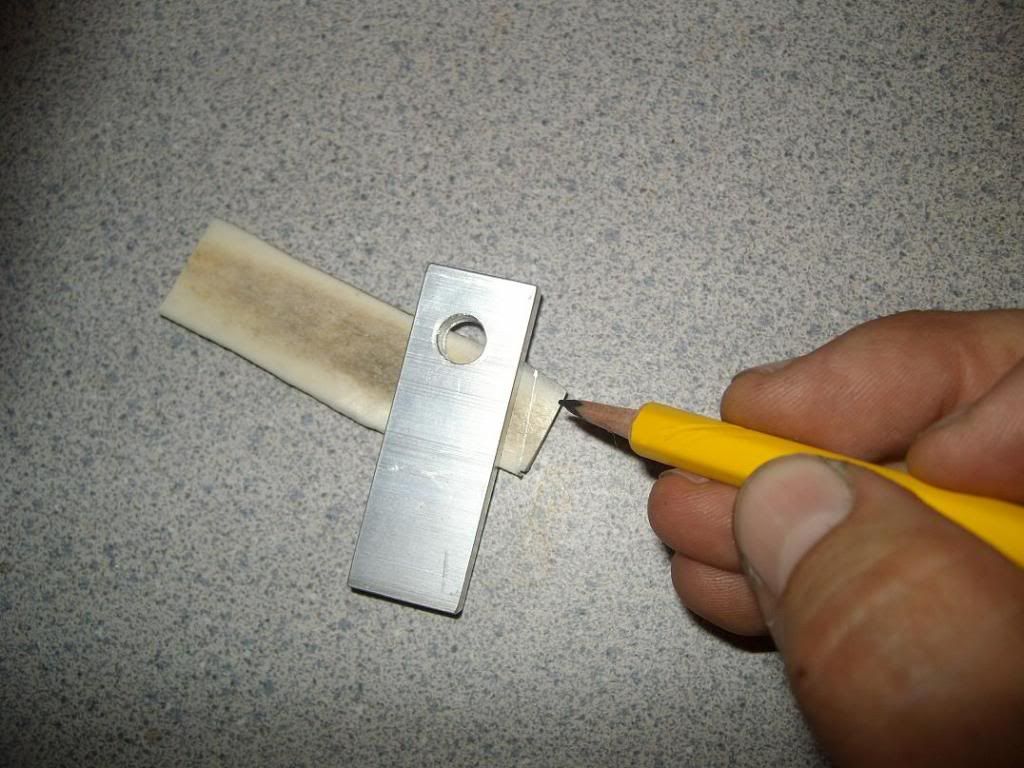
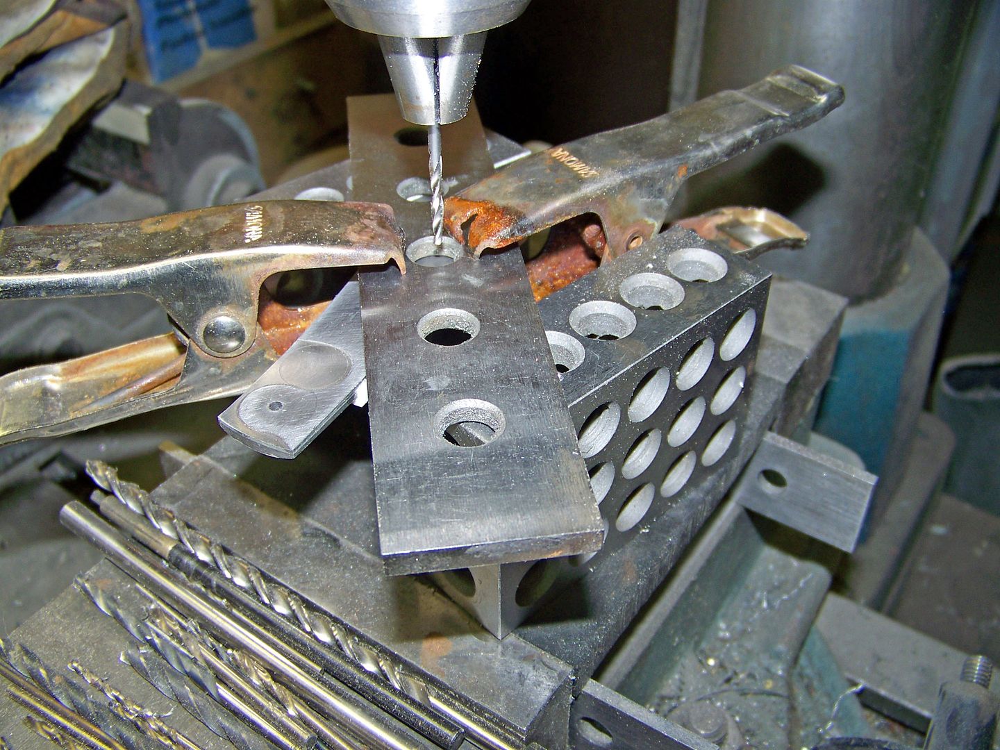
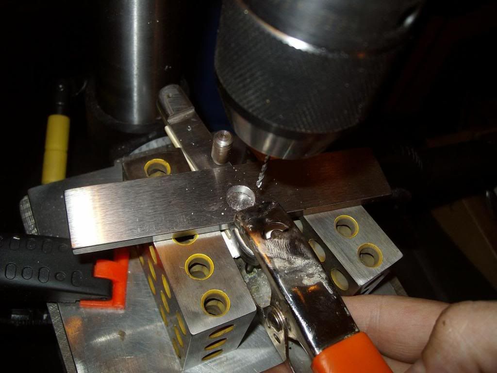
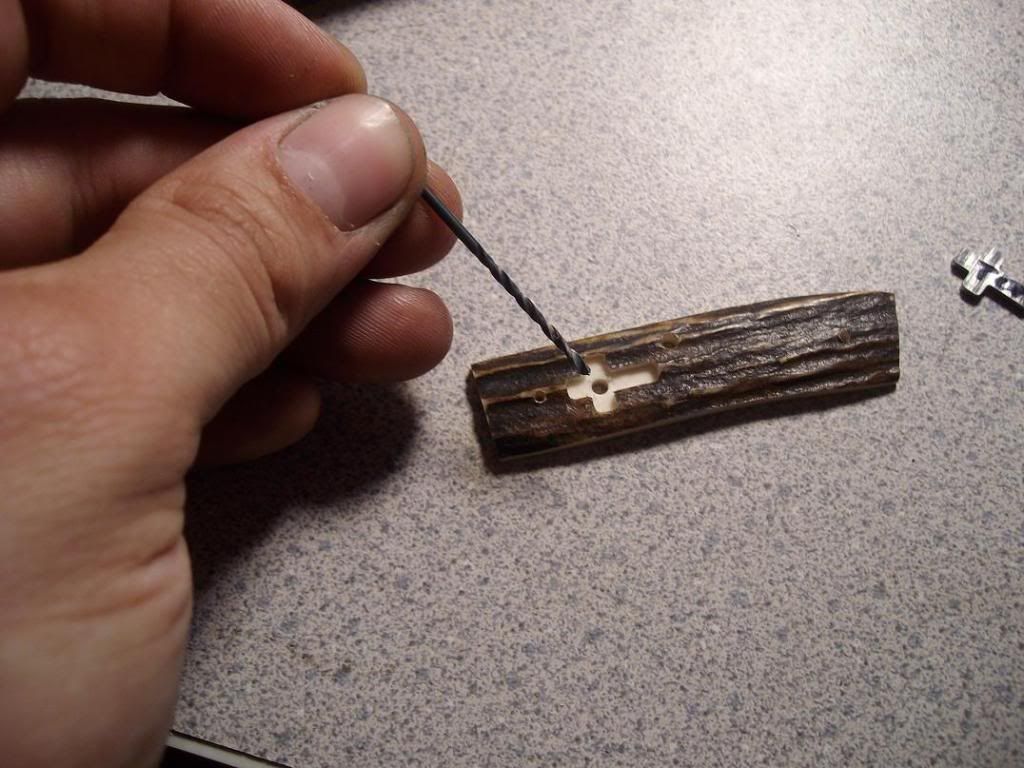
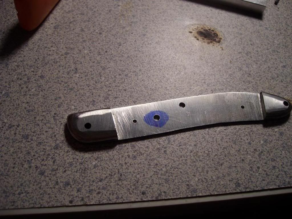
A small hole needs to be drilled in the center of this pocket for the shield pin. I chose to go with a 3/32" because I knew that the 1/16" pin on the back of the cross may not be in the exact center. This way you will have a little room for error-
slipjoint105.jpg


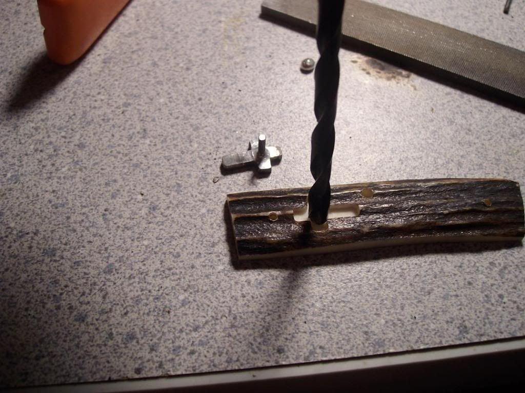
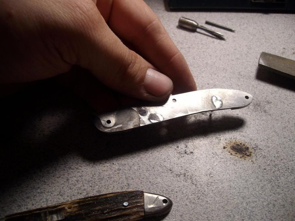
Take a larger drill (I used a 3/16") and twist it by hand on the hole you created earlier with the 3/32". Later we will solder a pin to the back of the shield. This will relieve the scale so that the swelled area of solder around the pin on the back of the shield will have clearance. You want the shield to sit down in the liner flush, not stop because something is keeping it from seating :)-
slipjoint107.jpg


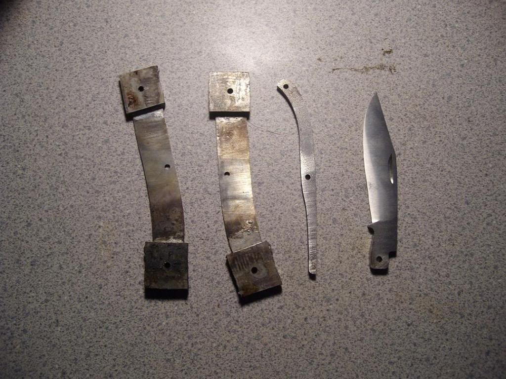
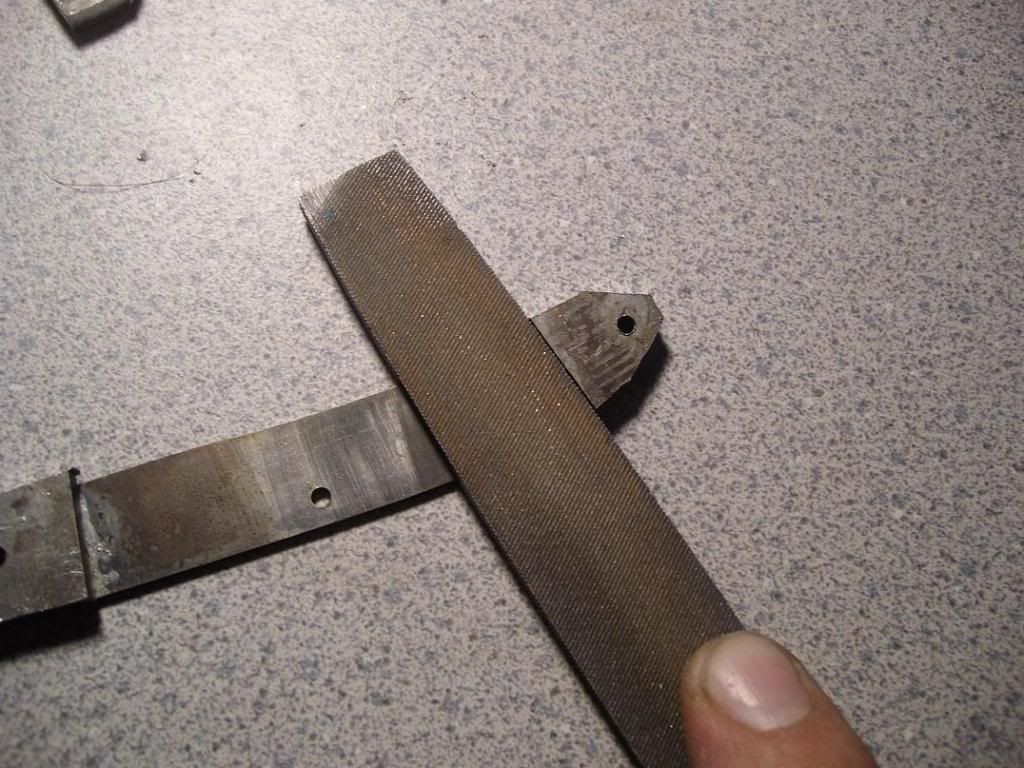
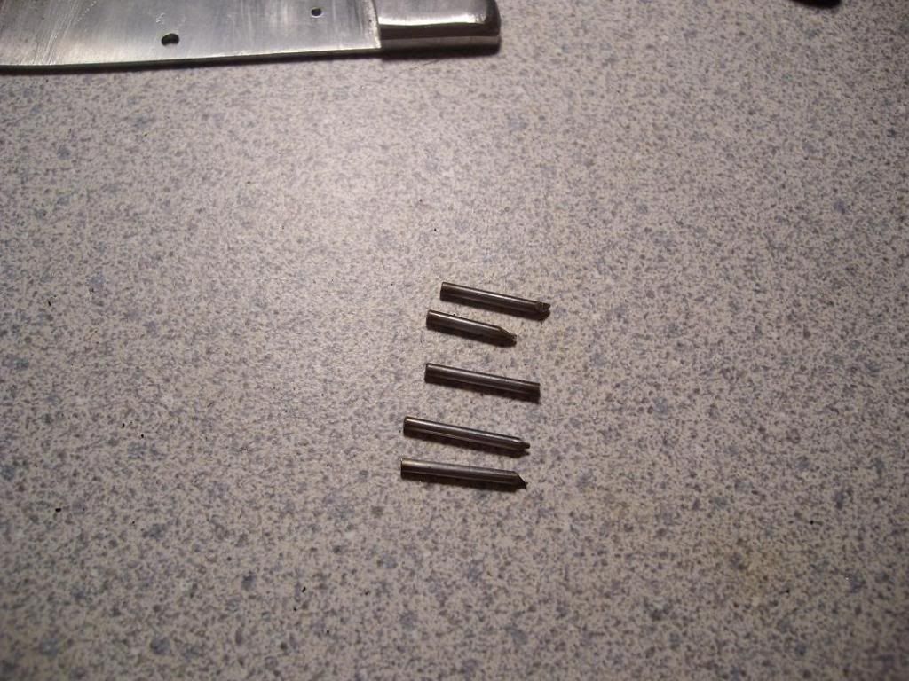
Here I cut 5 small 1/16th 410SS pins. I squared off one end of each. One is soldered to the back of the shield, the others are for each end of the scales-
slipjoint106.jpg


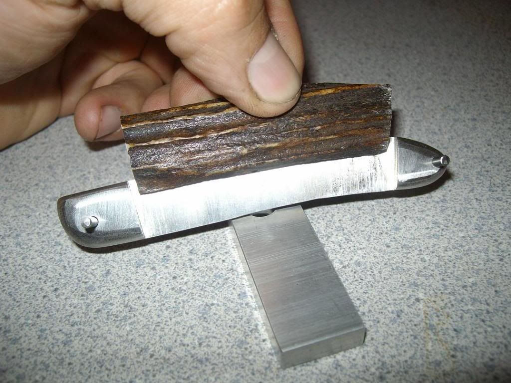
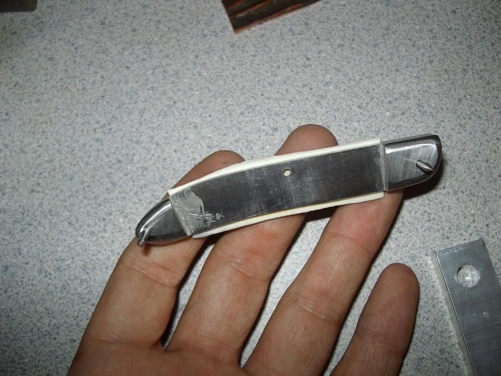
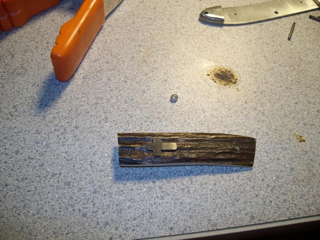
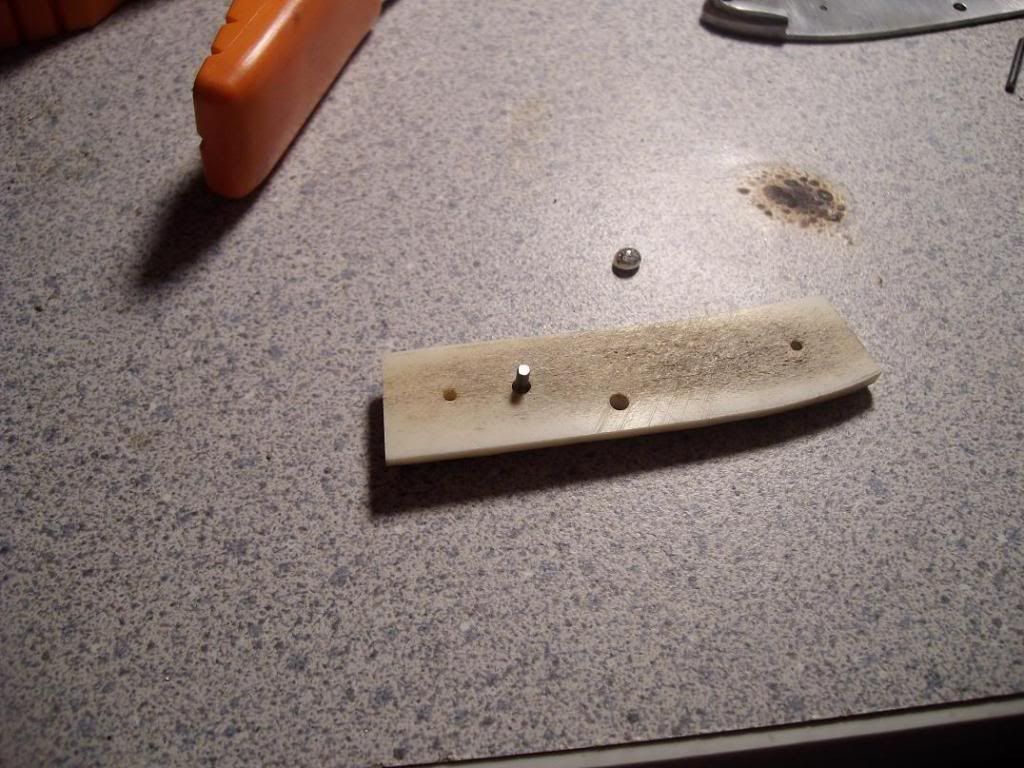
Here is the shield seated in the scale. The next pic is the pin protruding through the back-
slipjoint108.jpg


slipjoint109.jpg


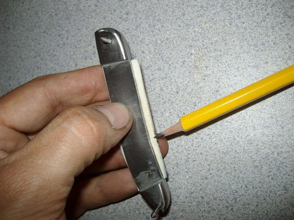
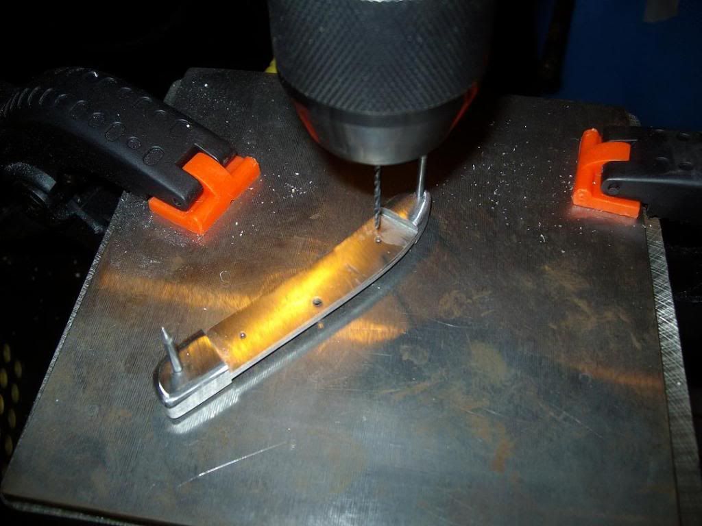
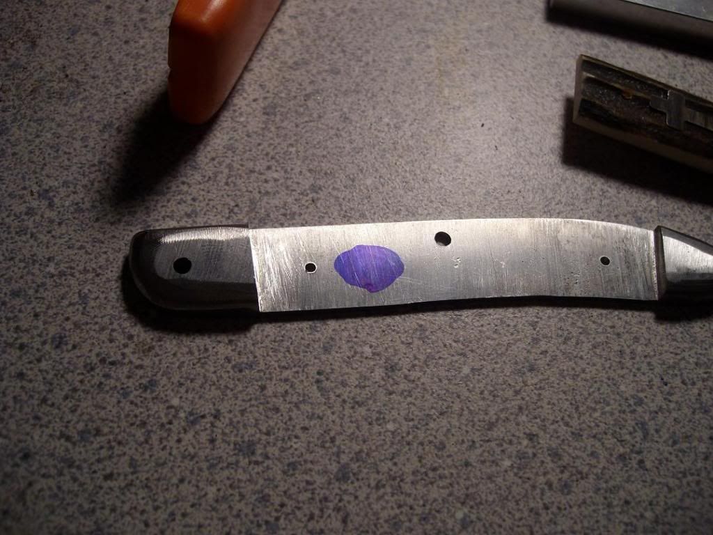
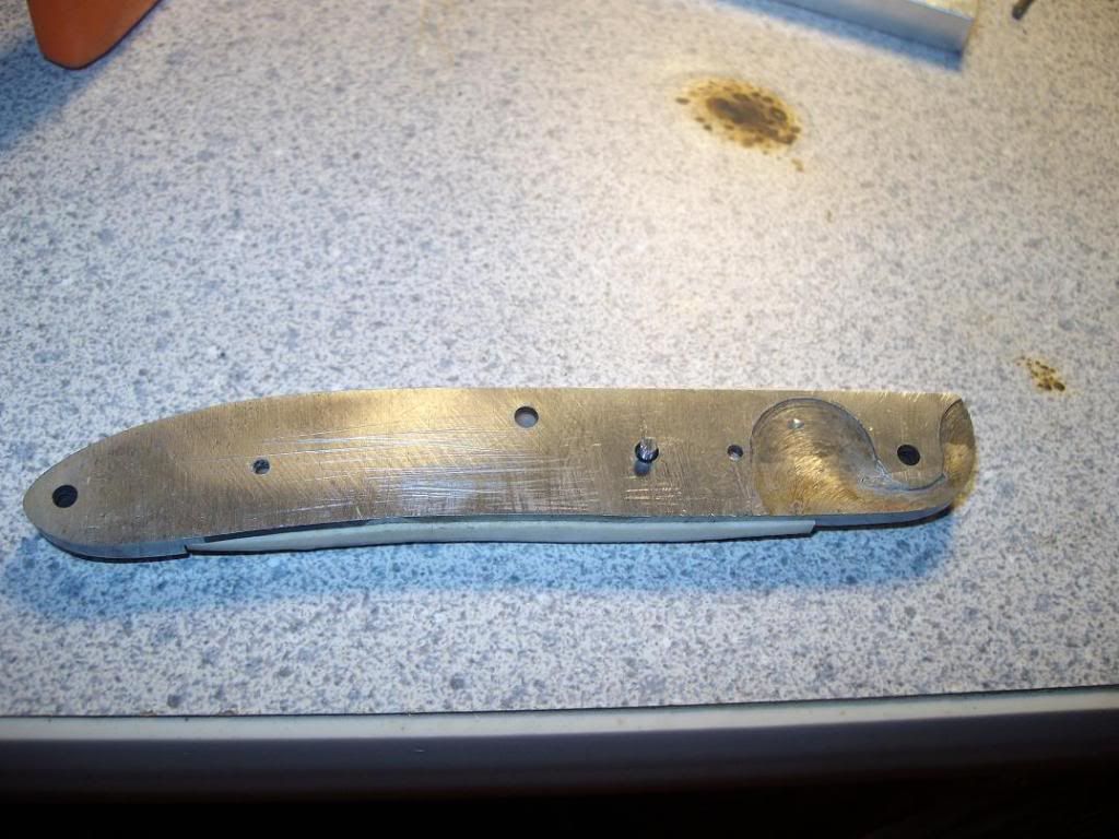
Next you need to mark the liner and drill a hole here for the shield pin. I used a 3/32 here too, just in case-
slipjoint110.jpg


slipjoint111.jpg


In this picture you can see the shield pin coming through the liner in the hole we just drilled-
slipjoint112.jpg


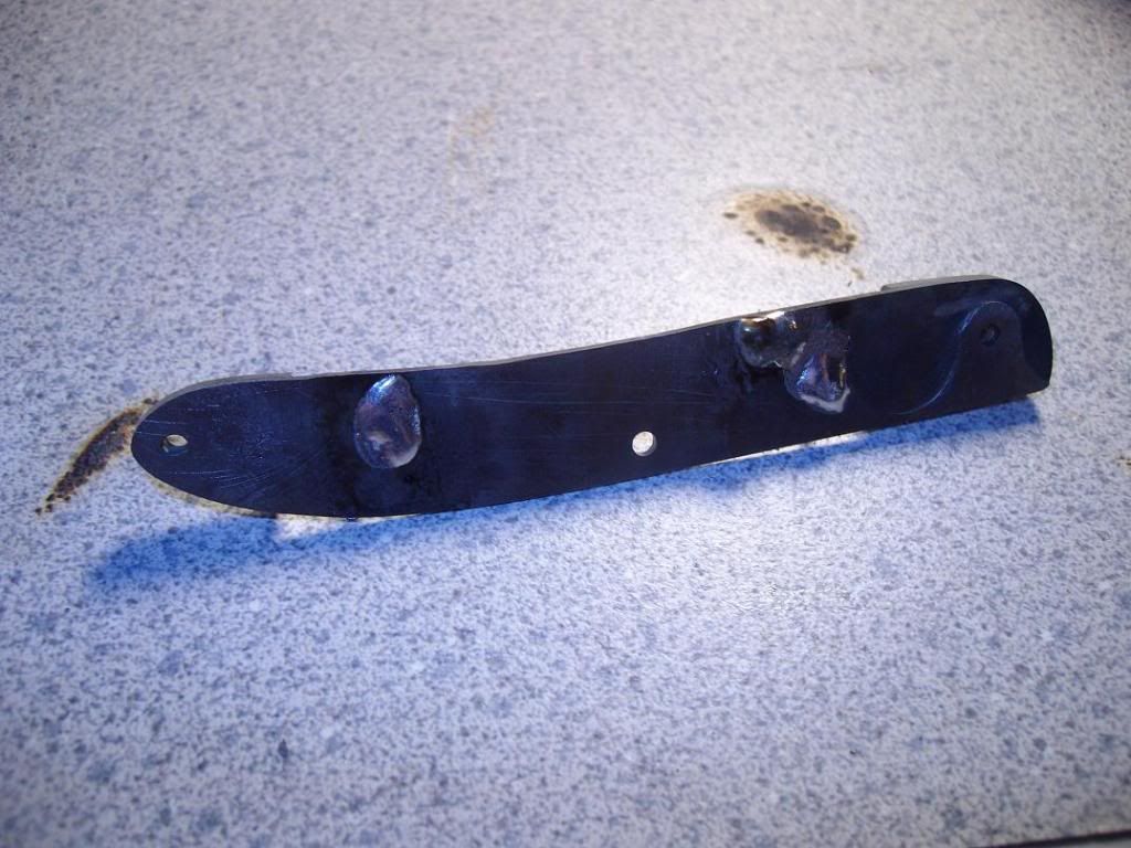
I soldered the back of the pin to the liner. I'm not sure if the other makers do this, but it was all I could come up with to secure this thing. It was very hard to do this because not only are the scales sensitive to heat, more importantly the bolsters are. just the right amount of heat will melt their solder bond and turn them loose. Be careful where you put the heat.

I also chose to solder my scale pins to the liners. do this step first, before you put the liners on, that way the heat will not affect the scales. After everything is cooled you can slide the scales down over the pins. The only one that remains to be soldered in the end is the shield pin. Again, be careful with the heat. I also super glued the scales to the liners-

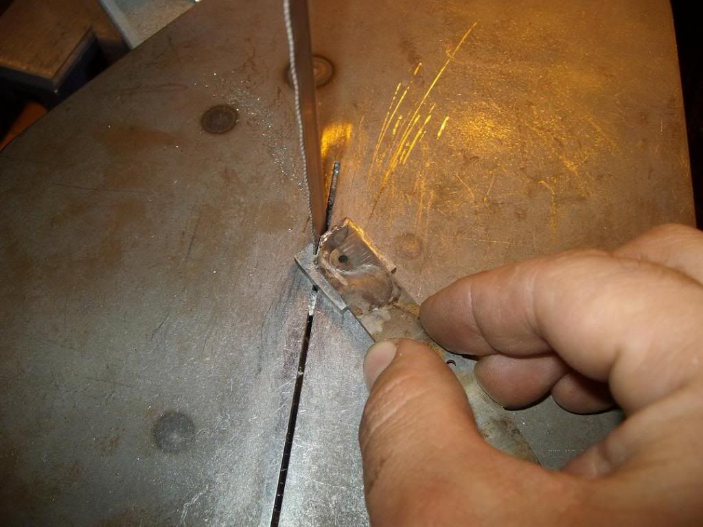
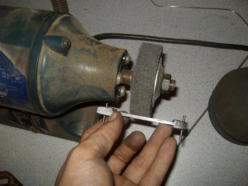
Soldering the pins to the liners -
slipjoint114.jpg


slipjoint115.jpg


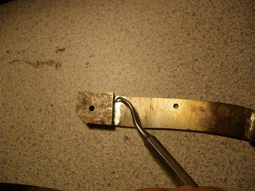
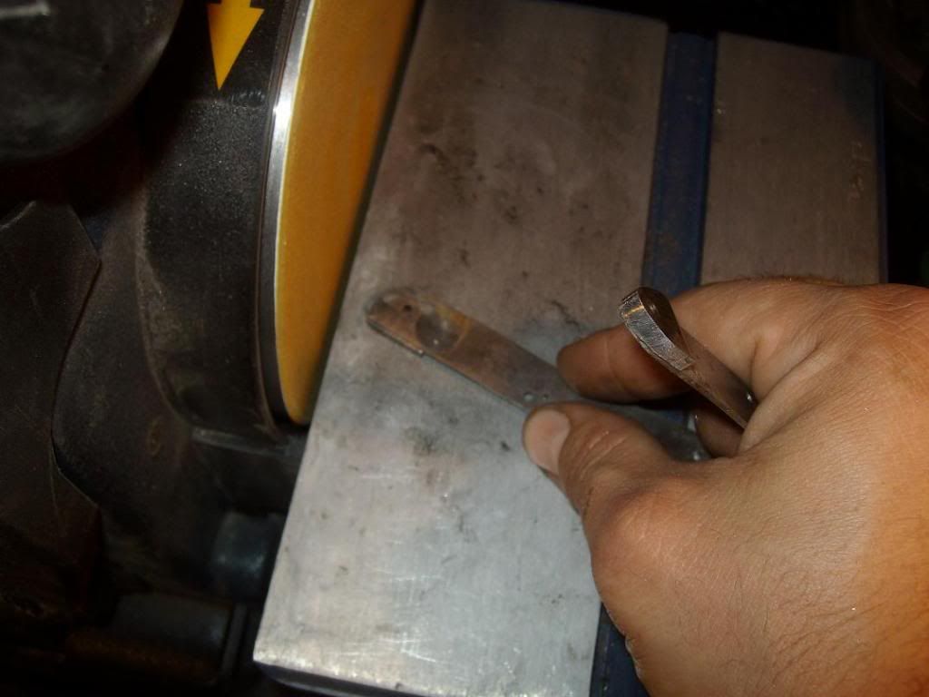
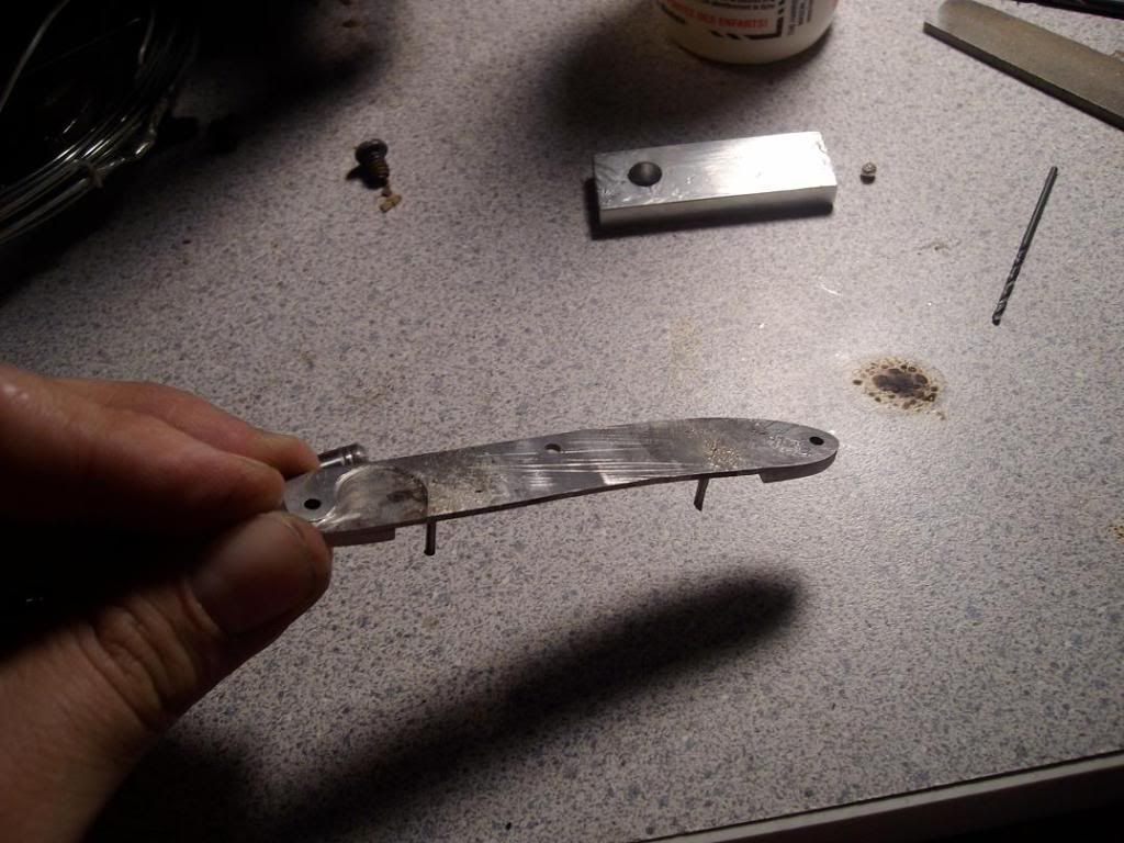
In this picture you can see that the pins have been soldered and I have started to file off the solder to bring the liner back flat. The solder will fill the minute voids between the pins and the liner-
slipjoint117.jpg


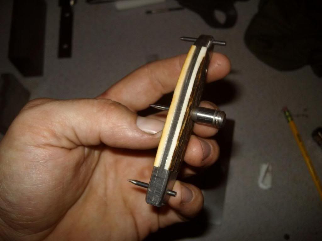
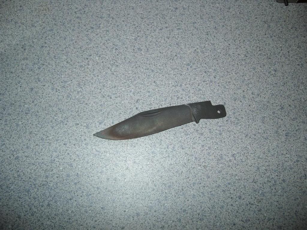
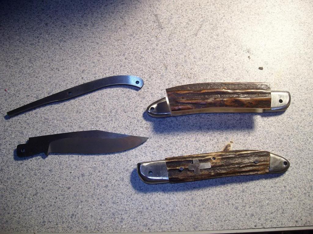
Here I'm placing the other scale on. Also in the picture is the spring and blade, which have now been surface ground. I brought them both down to .096" thick. That's a hair over 3/32". You can also see how i will have to do some finish grinding on the blade, to get it to the way it will look finished.
slipjoint116.jpg


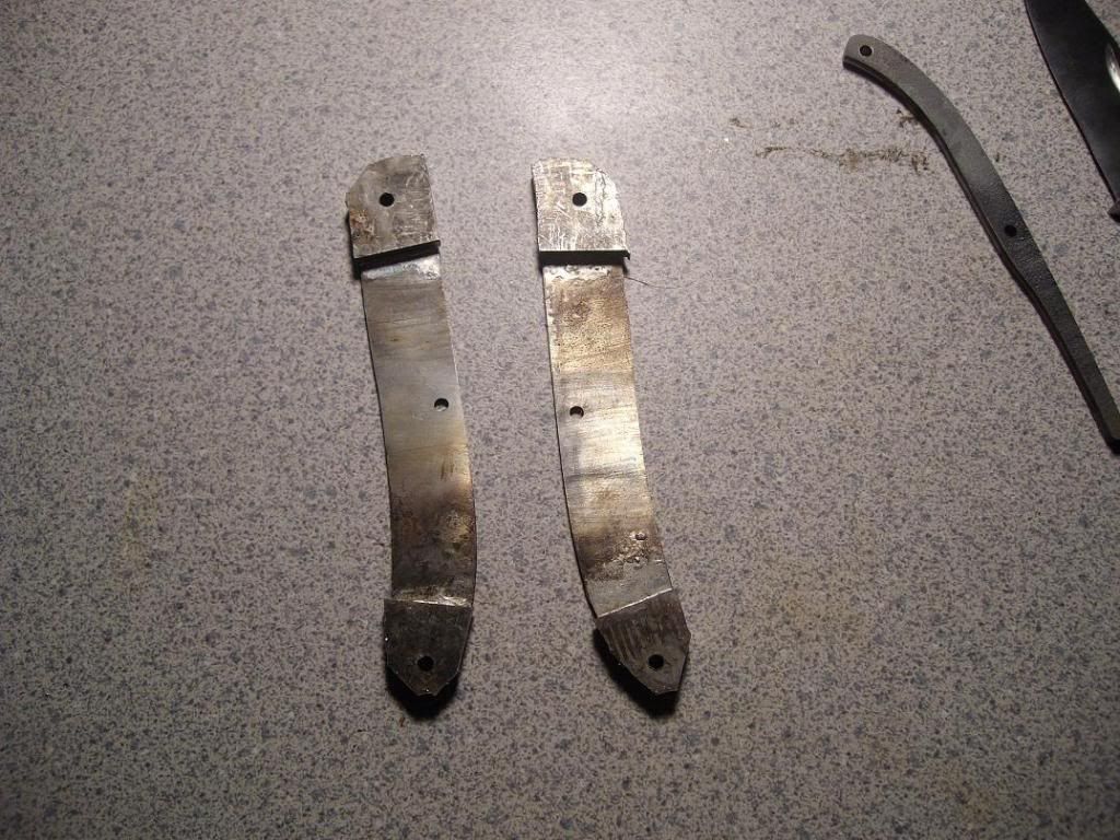
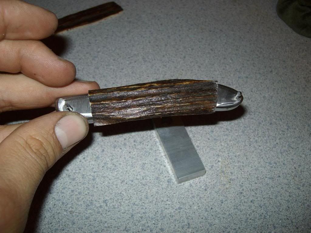
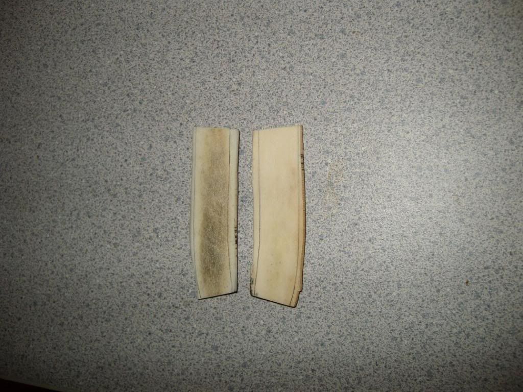
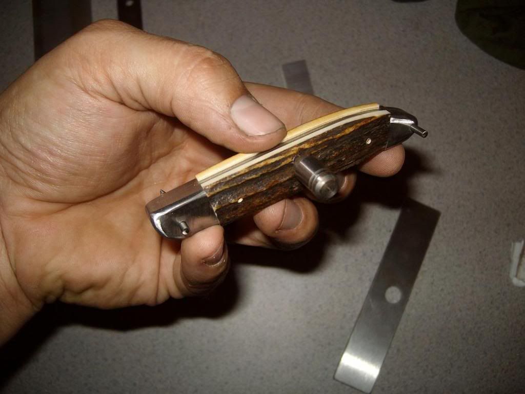
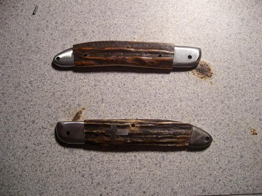
and here are the fnished handle assemblies-
slipjoint118.jpg


On the homestretch now folks. All I have to do is etch my name on the blade and pin it together. A little final sanding and this thing will be finished. I should be able to work on it some this week, and maybe get through with it.
 
Back
Top