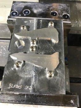
...
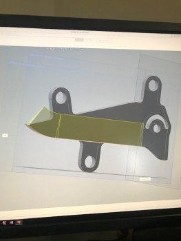
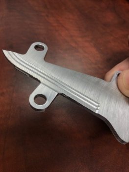
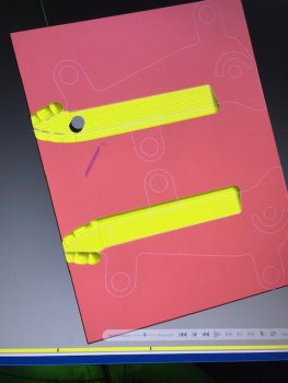
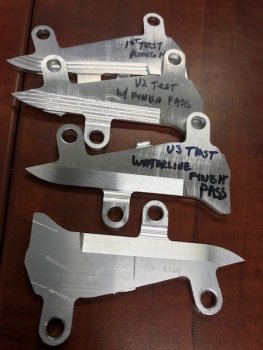
So getting this bevel modeled into the blade profile should be easy.
It took three days and dialing a friend to get it figured out.
It went like this:
model up the profile (easy)
make a swept cut for the bevel (harder)
notice that the bevel edge is not even. (huh?)
watch videos ( there are ZERO videos about this using solidworks)
try this, try that, wave a chicken foot over your head,
go home and try again tomorrow.
(tomorrow) find anything else to do in the shop other than sit at the computer again
(next day) beat yourself bloody trying multiple sweeps, get some to work but the dang edge thickness is still all over.
(next next day) call your buddy Travis who eats this stuff for a living, he tells me a different approach and a couple hours later it's done.
For the record if this makes sense to you.
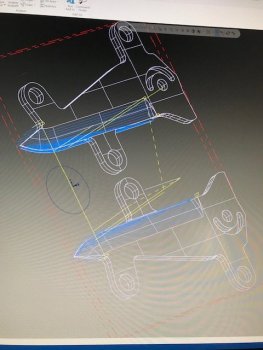
I had been creating a plane on the tip and sweeping back using a profile line and fully defined V shaped cutter. This gives a bevel on both sides but has uneven edge thickness. Try to keep tweaking and walking it in. It's madness.
Travis's suggestion:
Create a perpendicular plane at the plunge, create a center of blade plane, than create an offset plane from the center (this will determine edge thickness - offset .01" gives you a .020" thick edge) sweep cut one side using the offset plane profile, mirror the feature.
Seems like it would work but I couldn't get the mirror feature to properly duplicate it.
I finally noticed some vestigal zero thickness geometry left over the sweep cut. I thought it would be ignored, it wasn't.
I redid the sweep cut by using an offset profile line that eliminated the dangling geometry.
Boom, mirror function now works perfectly.
It's insane how one stupid little thing can really eat up time.
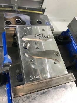
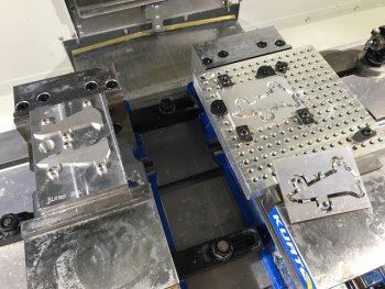
I should be able to take a picture with my phone, text it to the CNC controller, throw the material into the CNC, hit green and walk away.
