CNC WIP - small flipper.

I have been using a shop vac during the cutting. I stick my head in the side window and vac up the dust as it is cutting. If I end up making a production run of composite scales I'll have to figure out how to get a vac hose in place and leave it on during the run. After doing this a few times, I think a decent CNC router with tool changer and dust control would be a better way to go for scales in any kind of volume.

BossDog you’ve probably thought of this already but when I worked in a machine that cut lots of carbon fiber, they had it set up with a really powerful shopvac that sucked most of everything out and they just ran it dry with no coolant.
 
...

So getting this bevel modeled into the blade profile should be easy.
It took three days and dialing a friend to get it figured out.

It went like this:
model up the profile (easy)
make a swept cut for the bevel (harder)
notice that the bevel edge is not even. (huh?)
watch videos ( there are ZERO videos about this using solidworks)
try this, try that, wave a chicken foot over your head,
go home and try again tomorrow.
(tomorrow) find anything else to do in the shop other than sit at the computer again
(next day) beat yourself bloody trying multiple sweeps, get some to work but the dang edge thickness is still all over.
(next next day) call your buddy Travis who eats this stuff for a living, he tells me a different approach and a couple hours later it's done.

For the record if this makes sense to you.

I had been creating a plane on the tip and sweeping back using a profile line and fully defined V shaped cutter. This gives a bevel on both sides but has uneven edge thickness. Try to keep tweaking and walking it in. It's madness.

Travis's suggestion:
Create a perpendicular plane at the plunge, create a center of blade plane, than create an offset plane from the center (this will determine edge thickness - offset .01" gives you a .020" thick edge) sweep cut one side using the offset plane profile, mirror the feature.
Seems like it would work but I couldn't get the mirror feature to properly duplicate it.
I finally noticed some vestigal zero thickness geometry left over the sweep cut. I thought it would be ignored, it wasn't.
I redid the sweep cut by using an offset profile line that eliminated the dangling geometry.
Boom, mirror function now works perfectly.

It's insane how one stupid little thing can really eat up time.
I should be able to take a picture with my phone, text it to the CNC controller, throw the material into the CNC, hit green and walk away.
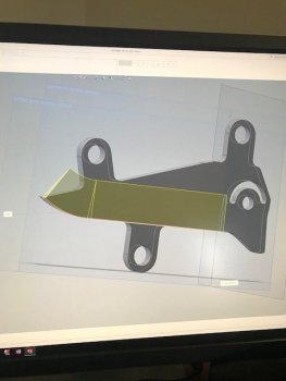
sweep cut.jpg
 
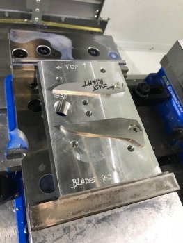
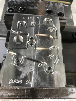
managed to make a fixture for the blades.
It's 1" aluminum. Something I have lot's of end cuts of. Once I get this project all proofed out and developed, I'll switch the fixtures out to 1" steel.
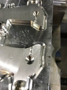
Anyway, this fixture will hold two blades and allow me to mill the bevels, arc slot and pivot hole in hopefully a fairly rigid set up. I have my doubts. I think the hold down screws will need some help with bumper pins to keep things aligned.

The large hole is used for touching off with the wireless probe to set G54 X and Y. I'll touch off on the stock for Z.

I have two sample blades laying on the fixture to kind of show where these will be positioned. Next I have to mill some more sample blades out of 1/8" aluminum stock with the tabs in place. After I get a few of those I can start working on tool paths to mill the bevels in along with the rest of the features.

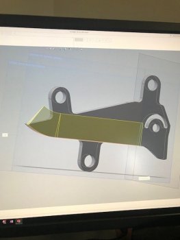
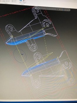
The Solidworks pic on the right shows the blade with the tabs in place and the cut sweep for the bevels.

The work flow right now requires me to mill out the blades blanks in a separate op and then move to this fixture. At some point I'll work on combining those two ops into one. I'll need to work on nesting several copies on one fixture first and that can wait. For now if I work on two parts that gives me access to both sides, I can easily scale up from there.

as always, any feedback or advice is appreciated. This thread is not a tutorial. I would have to know what I am doing for that.


IMG_3385.jpgsweep cut.jpg
 
good progress today.

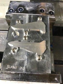
I milled out some extra blade blanks from aluminum and they fit perfectly in the indexed fixture.
Tomorrow I'll work on making some bevels in the blades. I think the aluminum is going to chatter and move around quite a bit, even with the 3 point hold downs. I'll run some in aluminum and then try some mild steel to proof the speeds and feeds.
IMG_3391.jpgIMG_3386.jpg
 
I know zilch about this kind of stuff, but with your ambition to learn how to do this and the stage your at it certainly looks like your going to be putting out some fine blades soon Boss, good luck.
I had somewhat of a hard time just comprehending what you wrote, but reading thru the lines, it seems you'll get this. :D
 
I made a test pass yesterday on one bevel on one blade to see how the roughing tool path was working. It wasn't.
The depth of cut at the edge is too shallow. In other words, the edge thickness would end up around .050" thick. I want .020" on the edge. This had me stumped for a bit and I had to think it through.

I went back and made some changes to the roughing pass by extending the containment boundary. This added another .010" to the depth but it is still not deep enough. but the finishing pass cleans that up and gets it where I want....I think.

I'll cut another part today and see how that comes out.

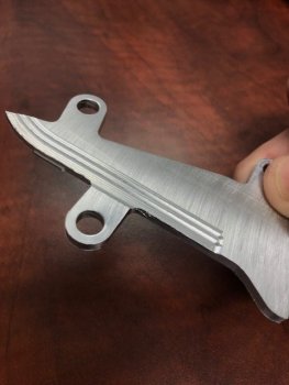
This is an aluminum test blade using a 3/16" ball cutter.

IMG_3395.jpg

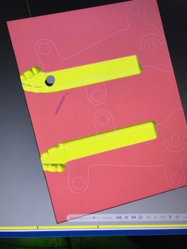
Below is the verify feature of Mastercam. It is animated and shows how your finished part should look. Looking at the tips of the blades you can see where the ball cutter drops off the edge. I had to set Z limits to avoid the cutter from plunging past the blade thickness into the fixture. The pink material represents the metal. Really, there is only metal for the blades and it is not a flat sheet as you see it here. I'm sure I could model it so that didn't look like a flat sheet but there is a benefit to showing it this way. Now I can see the plunge at the blade tips and make sure I'm not taking too much or slamming down into the fixture.
IMG_3398.jpg

In Mastercam you preview the tool paths (blue lines) and make decisions on how the tool is going to move. I am using a different roughing tool path for the top blade so I can see the difference on how they cut. My worry is the finish pass will end up taking too big of cuts in some places so I will have to see if and where that happens.
IMG_3400.jpg
 
Today was a good day.

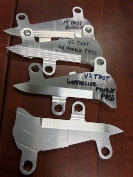
I ran a few test passes (one side) tweaking the tool path on the bevel for a decent finish. I changed the toolpath for the V(ersion)3 test to waterline for the finish passes. I also ran both blades, flipped them in the fixture and did it on the other side. This gives me at least some idea on how to run parts on both sides so they index properly which was the most important part of the day for me.

I wish I was faster at this. If I had to depend on this to make money and feed my family, I'd be divorced and starving.

IMG_3404.jpg
 
Looking good sir! What’s the stepover or scallop height your using for your roughing and finishing passes? It’s been so long since I’ve done any programming or setup on a CNC that I’m not even sure if I’m using the correct terms.... Anyway, not critiquing, just curious.

I wish we used MasterCam at work. That’s what I learned on in college but they use a super old version of Surfcam on an ancient computer that still posts the code on floppy discs lol. Thankfully I haven’t had to do much CNC at work cause I’m the “manual” guy now but I’m not sure I’d wanna do anything on our dinosaur software after using MasterCam and seeing how powerful it is.
 
Step over is .0015” using a 3/16" ball mill.

Floppy discs. That is old.

I've heard of several old copies of surfcam still being used. Mostly from guys attending Mastercam training classes. You could hear them gasp at what MC could do compared to their old software. They couldn't wait to switch.
 
Not a lot of machine time today.

I did spend a little time on the blade fixture.
I drilled and reamed the pivot hole, milled in stop pin arc slot and then profiled all around the blade profile.
Tomorrow I'll mill .005" to .010" off the top to remove the burrs sticking up from this process.

The reason for these relief areas is to give chips a place to go and also to minimize burrs from bumps, handling, etc in the fixture that can really create some tolerance issues.

I used a dremel vibe tool to mark the fixture plate originally. I'll have to start putting some milled engraving fixture ID names/numbers in the future.
Making the fixtures is almost more work than making the parts.

IMG_3407.jpg
 
Making the fixtures is almost more work than making the parts.

LOL! Almost always...a point most folks don't get...you just load material in the hopper...wave a pic of your project in front of the screen..and then hit the green button...right? Lol!
 
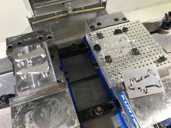
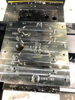
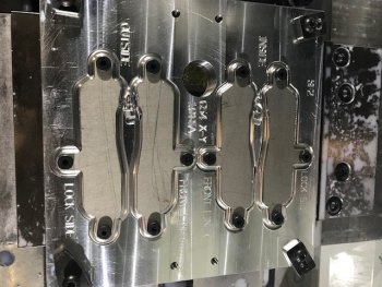
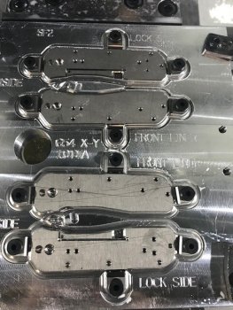
Finished working on the fixture for the liners/scales.
This is the 2nd attempt at making this. The first one slipped a bit and had to be scrapped. I had to re-zero the Kurt vises in the CNC as they had moved quite a bit. I need to work into my routine a periodic check of the zero on the vices.

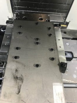
Typically in a production set up you would often use a waterjet to cut the parts and then fasten them to your fixtures for milling. I want to be able to profile the parts on a fixture and then mill them. I have not done any math to see which is more economical, waterjetting the profile or milling them out. Most people I talk to use waterjet cut parts.

Milling the profile allows me to do very small batches and I don't have to meet a minimum or wait for waterjet parts to show up. If I scale up and have some parts waterjet cut, I can easily modify the program and use this fixture.

This fixture is set up to run two sets of parts here. The top two positions finish the inside, the bottom two finish the outside. There isn't any outside work needed on the liners but there will be for the scales. This knife project version is a liner version, the next one will be the same model but in a frame lock style and it will also use this fixture.

The large hole is to swing in the fixture using the wireless probe to set the X-Y Origin (G54). I touch off Z using the stock in the fixture.

My planned process is to clamp down two small (or one big) sheets of Ti for the liners. Run a program to drill the tab holes, stop the machine and screw those in place. Once it has the tabs screwed down, continue to run the program to profile away the excess from the sheets. Once the parts are profiled I can mill/drill what ever needs to be done on the inside and outside of the parts. This will be the same basic process for the g10 scales using the same fixture.

Figuring out how to make these fixtures was a lot more work than milling out the liners on a general purpose fixture plate.
Hopefully this all works.

IMG_3429.jpg
 
I know this is trivial for someone that has done this but it wasn't for me. I had to think about this so hard my brain hurt.

I had a huge issue with Mastercam getting Z zero origin set. I finally ended up setting Z zero at the top of the fixture. Normally I would set Z zero at the top of the material but it was "stuck" and wasn't coming unstuck. I had to talked a little bit to Les George last week and he mentioned he sets his Z zero on the fixture and programs positive Z levels. Not sure I would have figured a work around for the Mastercam issue as I had never seen it done before. It worked.

This was about testing my fixture set up and work flow plan to rough out liner profiles on a sheet into tabbed parts I can continue to machine.

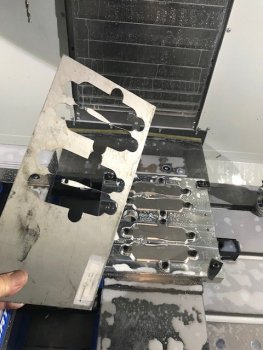
The first step was to clamp down the sheet using the outer clamps.
drill the liner tab holes, screw in the tab hold down screws, then reclamp with the 4 outside hold downs to keep the skeleton from moving around.
IMG_3433.jpg

After profiling the liners, the skeleton comes out....
IMG_3438.jpg

...leaving the profiled parts (liners) ready for the next op. I will have to make some tool path adjustments so there isn't a flimsy loose bit of skeleton that can flop into the cutter and ruin my day.

...IMG_3441.jpg
 
Last edited:
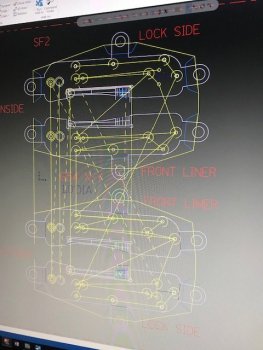
Most of the day was laying out tool paths for 4 liners with ops on both sides.
This looks pretty cluttered as it shows all the tool paths at once. In practice, you would usually only view one at a time.

I also fired up my copy of Gwizard and finally spent some time learning how to use it. Gwizard is a stand along program that helps you figure out the feeds and speeds. Mastercam has a built in function feeds/speeds calculator but Gwizard takes it several steps past mcam. I will be using Gwizard going forward now that I have an understanding of what it can. Recommended.

There are 8 tools for this job and it will take an hour or so finding them, setting them up and touching them off.

Cycle time on this run is around 37 minutes according to the verify function in Mastercam. This doesn't include the time it takes to flip the parts but that shouldn't take but a few minutes.


IMG_3452.jpg
 
Kinda fooling around with the embed media here more than anything BUT.....

This is the visual verify function in Mastercam for the previous post.
The red sheet isn't exactly accurate in that the parts are already profiled out but it serves the purpose of showing where holes and cuts are made.
The lock bar cut is .046" wide using a 3/64" cutter and is a bit tricky to get right.

View media item 70
 
good news, bad news.

Good news, I got this set up to run most of the way thru.
Bad news, there were a few problems I need to correct.
Good news, no big deal and it's just part of the learning curve.

On the first attempt I broke the spotting tool in the first 30 seconds as I didn't set retract clearance properly and it hit one of the hold down screws. I knew to look for that and it still happened. Not the end of the world. I adjusted the retracts and changed the sorting order of the holes to avoid the hold downs.
I found this would have happened two more times during the whole program run so I fixed those also. It's still spooky to see the cutter pass just fractions of an inch from the hold downs.

After that was fixed I ran it again.
This time I found I had the wrong tool loaded to drill the pivot hole so that is massively over sized and I completely missed the op where I mill a pocket for the bearings. It's really impressive how many mistakes you can make doing this.

These parts are scrap but I can still go back and run the bearing pockets to proof that out.
I will flip the parts and give each hole a slight chamfer.
I will also need to run a corner round on the edge where your index finger hits when flipping out the blade. The edges are sharp otherwise and need to be softened a bit. I'll test that on these parts also before I make a new set and run the program at full speed.

Once I get thru these, I'll inspect them for any adjustments to depth of cuts, finish and run a new set. After that I will start working on the g10 scales.

I have to say this whole thing has been insanely complicated to learn so far but it also one of the most interesting and entertaining processes I have gone through.


IMG_3453.jpg
 
"I have to say this whole thing has been insanely complicated to learn so far but it also one of the most interesting and entertaining processes I have gone through."

Excellent!! This stuff beats playing Trivial Pursuit any day! (or any other brain challenging game for that matter)
 
Back
Top