U Weld 2x72 Grinder kit support thread

BossDog

KnifeDogs.com & USAknifemaker.com Owner
Staff member
This is a placeholder thread for information and assembly of the U Weld Grinder Kit.

Overview: the U Weld grinder kit will be a full 2x72” grinder that is welded/assembled by the customer.

No Price or release date has been set. (but soon)

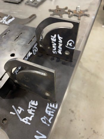
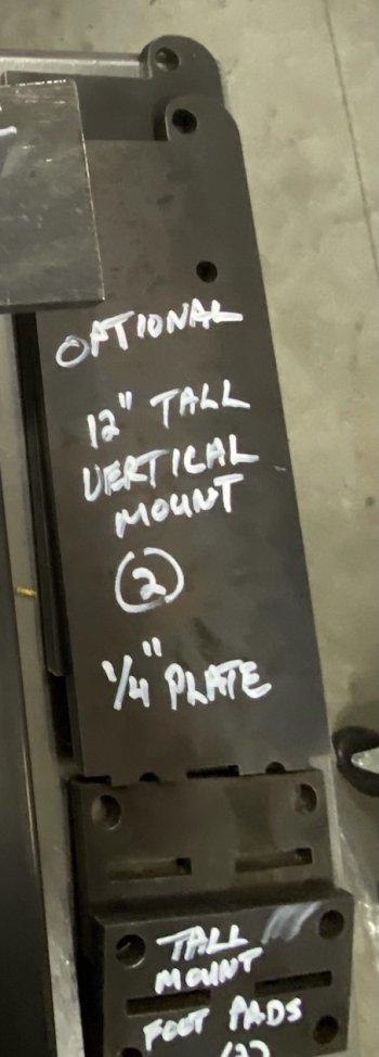
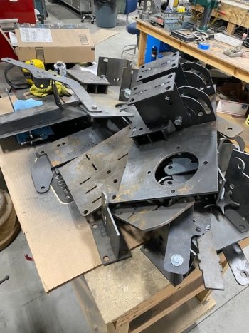
Having said that, the idea here is to put out a reasonably priced grinder kit using parts we cut in house using our CNC Plasma table.

Tools required:
  • A welder. Actual welding time will be less than 30 minutes by a beginner welder. The tab and slot design will make assembly easy.
  • 2 adjustable wrenches to attach and tighten wheels and some fasteners
  • a hand drill and 1/4” drill bit. There is one hole to drill after assembly.
Motor:
I suggest at minimum a 1.5hp variable speed motor. I usually put a 2hp or 3hp motor on shop grinders.
We are working on getting set up to sell motors and VFD speed controllers but that will take some time.

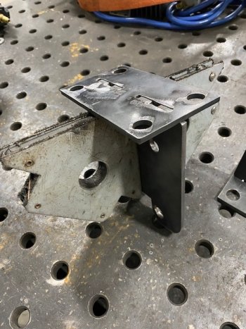
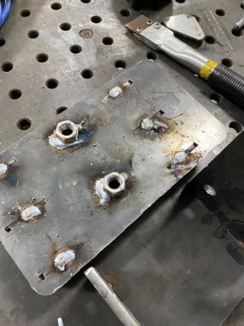
The kit will ship in a flat pack and assembles using tab and slot that the customer will weld together using simple button welds.

The grinder is direct drive design and will rotate 90 degrees for horizontal grinding.

The following posts will be edited as I develop the instructions for the build process.
 
Last edited:
This is what part of the kit will look like.
Not pictured are: wheels, fasteners, tension system (3 choices are being developed; a spring, a gas strut and pneumatic) and optional adjustable work rest.

You should be able to make out the tabs and slots. Note there are two vertical mounts. The optional 12” tall vertical mount allows the motor to clear the bench it is mounted to. The shorter vertical mounts require the back end of the grinder to hang off the back end of the bench to allow it to swivel 90 degrees.

The grinder is cut from a mix of 3/16” and 1/4” mild steel.

E2CD165E-519B-4765-884B-941070996918.jpeg

It is important the buyer is aware of the limitations of CNC Plasma vs Laser cut or Water Jet.
1. Plasma is significantly cheaper to purchase as a tool and to operate.
2. The resolution or kerf cut is less than laser or Waterjet.
3. All CNC plasma cut parts have a draft to their cut. So does Waterjet but some Waterjets have dynamic heads that tilt slightly to reduce the draft. Laser cut parts have minimal draft.
4. Cut quality can be quite good but their will be dross (slag) to clean up.

Below is an example cut on a part. The draft and cut quality can be improved by some tweaks to the settings and cut speed. We have spent quite a bit of time working on cut quality. You can see some draft here. All of the parts will have some draft.
AD551855-DA96-4BC1-BBEC-7836F79DEDBD.jpeg

Piercing a hole with a plasma can be ugly. The minimum size hole with a plasma is supposed to be around 1/2” as the smallest. Again, with some tweaks you can get smaller but not much and hole roundness isn’t as good as a laser. Some waterjets also make sloppy looking holes.

We remove most of the dross (slag) left from the cut. The customer will have some clean up also as the more stubborn bits may need a touch with an angle grinder and flap disc.

A91455E5-16D1-4DAD-890B-6D8CE2E4557E.jpeg

above you can see where the plasma arc leaves the hole but some stubborn dross is left to remove with an angle grinder and flap disc.
 
Last edited:
Good luck with that Boss! Your “no-weld” grinder plans were really well done and helped me get started in knife making. I’ve since bought a KMG-TX but I still use the no-weld one too.
 
This is the main plate. Everything builds off this. It is 1/4” plate.

2DECAB3B-FB27-420A-98B7-4130BEB1DA25.jpeg


Your first weld will be the tool arm sockets. You will weld 3ea tool bar holders and cage plate to the main plate.
Here you can see one of the holders in a slot.
54609C44-D967-40B9-890F-CEE52BCBCE53.jpeg

All 3 holders are in place. These are button welded on the back side. We will show that later with pictures and a video.

It is important but not hyper critical that your welds are square. If you don’t know what that means, stop here and buy the fully welded version.

NOTE: A few pieces are symmetrical but some are not. The tool bar holders must be oriented as shown. The ”short side” (look at the distance from the end to the tab) should be on the motor side or the grinder will not swivel 90 degrees.
B5B22785-1DBA-4690-91EA-1BE0BE4CA606.jpeg

Here the cage plate is ready to weld onto the tool bar holders.


ED814949-7220-499A-9DC6-8821B81504E8.jpeg

Above you can see the tab and slots. Your first weld is going to be small button weld in the notch on the tab. It is 10 second squeeze on the mig welder with almost no movement. Just fill in the notch, not the entire slot. You can fill in the slot later if you want but we are doing a quick button weld for now.

Also note the two holes. Weld a couple 1/2” nuts here as an alternate method of holding tool bars in place.
 
Last edited:
Now we are going to weld some nuts to the main plate and to the cage plate. These are used to hold tool bars in place.

We are going to wel 4ea 1/2-13 nuts to the main plate on the wheel side.
You will not use all of these at the same time as the handle “knobs” interfere with each other.

Weld 4 nuts on the wheel side of the main plate.
Weld 2 nuts on the cage plate (motor side)
8F3971FD-E2D3-4E1A-9C39-9C9809F6EB23.jpeg

These are easy to do. Thread a nut onto a bolt and drop the bolt into the hole and weld around the nut. Unscrew the bolt. Done.


11CB225D-7C56-4C44-ACF1-6CEC433E297F.jpeg

You will get at least 3ea of star knobs. These get welded onto the 1/2” bolt heads. They are large enough to get in each other’s way so we now have multiple points for these to screw into and not bump into each other.

Below, this shows how 2 of the star wheels are offset.
4928C150-F8EC-4B73-997A-689D4E036649.jpeg
 
Last edited:
Now we weld the swivel brackets to the main plate. Keep things square please.

The 1/2” hole near the bottom is the actual pivot point. The arc will allow a retaining bolt to be tightened but really just acts like a guide when tilting. These are welded to the motor side just under the (already welded) cage plate.

IMPORTANT NOTE: This part is easy to install upside down. Note arc is at the top and 1/2” pivot hole is lower.


BF4E82C8-DF6C-40EE-90F5-441419F2A08A.jpeg


Now weld the foot pads to the vertical mount. The bottom hole is the pivot point. The top hole in the tab is a retainer bolt hole simply to keep things from twisting when tilting up or down. In use, I’m not sure it’s really needed but it’s there.
8BF97D1D-C956-4529-8720-4C5D7B3F4057.jpeg

There will be an optional “high rise” mount. These vertical support plates are 12” tall and allow the grinder to tilt when the bench would otherwise block the motor. These taller mounts are 1/4” plate and heavier foot pads also. I have two grinders that tilt. One requires the bench to be out of the way for the motor to swivel, the other is on taller mounts that allow the grinder to tilt regardless of the bench.
Clear as mud right? I will try to get pictures of both later.

B735A9FC-96DB-4F47-8FD5-6EAAF632D3D5.jpeg

I will post another series of pictures when we bolt things together.
 

Attachments

  • FE20F1E2-BC36-46C5-86CC-6671831A53C1.jpeg
    FE20F1E2-BC36-46C5-86CC-6671831A53C1.jpeg
    823.4 KB · Views: 37
  • D41C6A25-2A09-4093-86BC-0706A648B073.jpeg
    D41C6A25-2A09-4093-86BC-0706A648B073.jpeg
    140.1 KB · Views: 3
Last edited:
The tension arm has 2 small swivel brackets to weld onto the wheel side. These brackets will hold the swivel tracking block. The swivel tracking block - not pictured- hold the tracking wheel and angle the tracking wheel for belt tracking.

To the right of the tension arm is the slack belt and platen attachment. It will swivel a bit if you prefer your platen or slack belt set up to be angled.

Note slots in the slack wheel attachment points. We will include 2” and 3” poly wheels. The slots allow easier adjustment for different wheel sizes.
To use as a flat platen bolt on the platen shown below.

E7B21FE4-BA47-4A21-B0CF-5B4B9E749F35.jpeg


The platen mounts via a set of slotted, form brackets. The platen will be 8x2”, drilled and tapped already. We will include a ceramic glass and JBweld to finish the platen.
F1D04382-6190-405E-A272-66F11004EBED.jpeg

It will look something like this.
3C597342-FAC4-4869-BA78-9419BBE869DA.jpeg
 
Last edited:
A static tool rest will be included. It is simply some 1/2 plate welded to a 1.5” tool bar. This simple tool rest is probably good enough for most people but we will also have an adjustable tool rest.
1CF9EE1F-6AA6-406B-AE9E-6C80F30889F0.jpeg


The optional adjustable tool rest is telescoping square tube welded in place with a tightening nut.
Below is an example. A section of 1.5” tube is welded to a tool arm. A hole is drilled and nut welded to the section. A vertical tube that fits in the section you just welded has a plate welded to the top. These are easy peasy to make.
59D464C2-A0A5-4BD9-9513-7EFA48DB84C3.jpeg
 
OK, time to weld.
We will start with the tension arm and the swivel brackets.
Keeping things square with a welding magnet. These things really suck as you think things are square and they aren't. Check it.

image001.jpg

Both are welded. Here is a view of the button weld. You are filling in the notch on the tab is all. You stand at least a chance of removing a part like this for a do-over if you just button weld it. If you fill in the slot and make a mistake, you are not getting it apart again.
image002.jpg

Here is the tension arm with the tension swivel brackets welded in place.
image003.jpg
 
Now lets weld the tool bar holder in place. The 5 pieces (main plate, cage plate and 3 tool holder parts) are all "dry" assembled and clamped in place. Don't be afraid to tap things with a hammer. If you weld much, you already know this.
image005.jpg

I am making sure things are perpendicular. This assembly likes to lean a bit. Take a hammer and tap the whole thing to plumb when it is clamped.
image004.jpg

A quick button weld with 6 on the motor side and 6 on the wheel side.
image006.jpg
 
Now we weld the main swivel brackets in place. Keep them square and note the orientation. It is easy to weld these in upside down. I did that and had to cut them out and flip them on an earlier build.
image007.jpg


Now we are going to weld some nuts to the main plate and the tool bar cage plate.
It might happen that a hole is a bit sticky when putting the bolt in place. I have designed the holes to be oversize enough to accommodate the 1/2" bolt that will run through it. Occasionally a bit of slag is still left or the draft of the hole cut is a bit steep so I will ream the hole a bit with one of these cheap step bit. Most holes will be fine.


I threaded a nut onto a short bolt, drop it in the hole, hold the bolt with my finger and give it a couple stitch welds around the nut. This bolt will get hotter than hot - even with welding gloves - so don't touch it for a bit.
image003.jpg

Four nuts on the wheel side. Note the splatter is from 1. Not grinding the foundry scale from main plate before welding and 2. the zinc coating on the nut. Don't breath the fumes when welding these nuts on. Also, clean up any foundry scale on surfaces that will be welded and you will get a better weld.

Here the 4 nuts on the motor side of the main plate are done.
image004.jpg

Flip your work over and add 2 nuts to the motor side cage plate.
Note the tool just to right. It is hardened steel square edge "chisel" used to chip off slag and dross. I use this to clean up dross from the CNC Plasma and welding splatter.
image005.jpg

Here it is a cleaned up a little. I used a wire brush on an angle grinder to clean up most of the splatter and the slag chisel for any stubborn beads still left.
image007.jpg
 

Attachments

  • image008.jpg
    image008.jpg
    146.1 KB · Views: 4
  • image005.jpg
    image005.jpg
    119.4 KB · Views: 4
Next we weld the foot pads to the vertical arc bracket. Pretty easy.
The foot pad is symmetrical so it doesn't matter which way it goes but the draft in the slot might make it easier to go on one way vs the other. Check your fit. Note the hammer to the right to get the tab to properly seat in the slot.

image008.jpgimage009.jpg
 
The optional 12" vertical mount shown next to the "regular" size mount.
image002.jpg

Here on this proto build, you can see the regular size vertical mount in place.
image003.jpg

When you tilt it 90 degrees the motor would hit the bench so it has to be mounted on your work bench or tool bench so the motor can swing freely. This isn't a big deal at all but it might be a space issue for some so we made two different mounts.

The regular mounts require the motor to hang off the back end. The tall mounts will still swivel and the motor should not hit the bench.
image004.jpg


Here is my Fellhoelter Uber Grinder. (we sell these and they are awesome) tilted. We use a Harbor Freight tool bench for this grinder and the motor has to hang off the back.
image005.jpg

Here is my Beaumont Metal Works TX grinder. (we sell these also and they are also an awesome grinder) It has tall pedestal mounts that allow it to swivel the motor over my work bench. In this case my work bench is 34" high so this grinder work area is chest high vs maybe a more traditional height of belly button high. I've learned to use it at the higher height and it really isn't an issue switching grinders that have different heights.
image006.jpg


Aside from the work rest, the welding done. It is super easy and fast. It took me an hour to weld this up and half of that time was getting pictures for this thread. You, if you like, after you have bolted things on and lined up all the wheels, go back and fill in weld the slots. In testing, I have found the button welds are enough. I took one of the earlier proto builds and dropped it several times to the floor to see what happened. Nothing happened. It all held and I got some chips in the concrete.
 
This is the pile of prototype builds. The creative process for me is messy.

image003.jpg

I will have to go through this pile later to see if I can salvage a complete frame or two.
image001.jpg

There are parts here from at least 4 different welders other than the one I am working.
image004.jpg

I started with one table and have expanded my work piles to 4 tables now. This really needs to get done. I am running out of tables.
image005.jpgimage007.jpgimage009.jpg

The plasma is loaded with both 1/4" and 3/16" so I can make changes and cut new parts on either thickness.
image008.jpg
 

Attachments

  • image002.jpg
    image002.jpg
    152.5 KB · Views: 9
  • image003.jpg
    image003.jpg
    137.4 KB · Views: 8
Looks like you've got a good product there Boss - isn't it amazing how expensive R&D is when developing a product?

Any idea of desired price point yet?
 
Looks like you've got a good product there Boss - isn't it amazing how expensive R&D is when developing a product?

Any idea of desired price point yet?
Metal prices are up 250% in the last 6 months but it still looks promising this will be competitive in price. I am still working on sourcing some parts so I haven't made much progress on a retail yet.
 
Back
Top