Cliff Fendley
Well-Known Member
I've had emails and questions on surface grinder conversions, where to get parts and if I had any pics of ones I've converted so I took some pictures of this last conversion I built. Sorry some of the pics are blurry but you can get the idea.
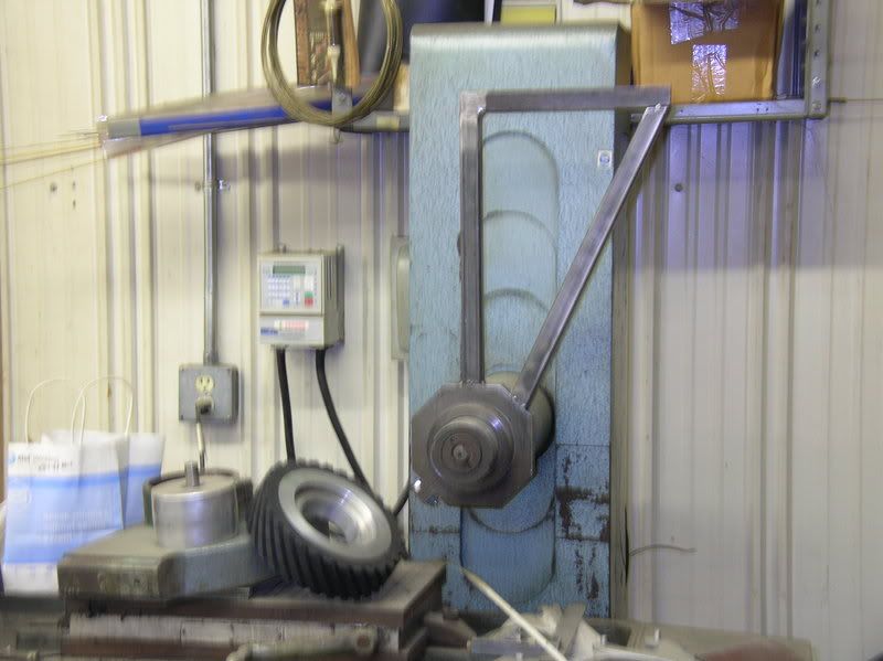
On my conversions I use a double idler set up that tracks very solid. It consists of a main frame that carries one of the idlers and a spring loaded pivot arm that carries the other idler which is adjustable for tracking. This is much like a KMG or Bader BIII grinder set up.
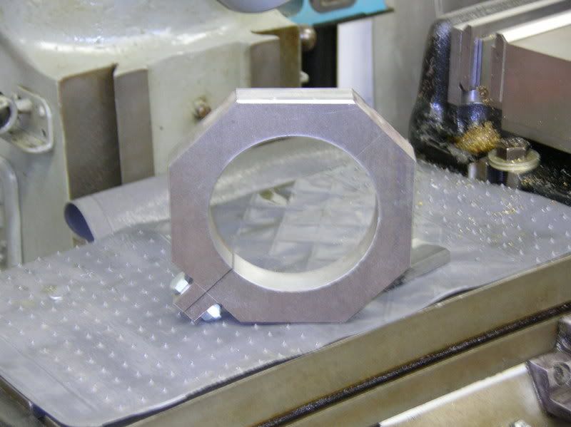
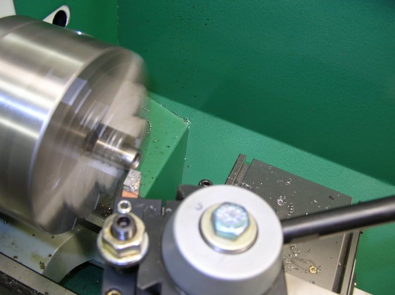
First of all you need to make a clamp ring that fits the spindle of the machine. This one is milled from one inch thick stock but I have also done this from round stock on a lathe. I make them one inch because I use one inch square stock for the frame.
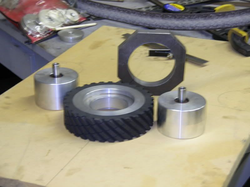
I had Bader make the contact wheel and idlers for me. This one is an 8x2 90 duro contact wheel. The idlers are crowned 2 1/2 x 3 with a .625 shaft that's threaded to except a 3/8 inch bolt.
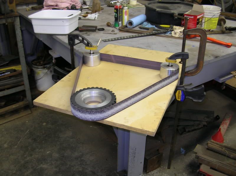
An easy way to lay it out is to use a piece of plywood that you can clamp the wheels in place. Take a belt and clamp the wheels where you want them and trace around them and then establish the center of them. From there you can draw on the board and build the frame to hold them in that position.
The clamping ring is in the dead center of the contact wheel and the top piece of the main frame is center of the right idler and will be drilled and counter bored to except the idler.
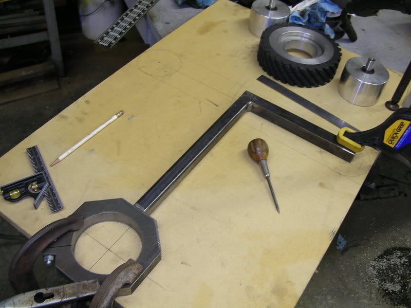
Its not necessary but it could be helpful to put the frame on the grinder after its built just to double check alignment. In the case of this one I built it so the 2 inch wide contact wheel would be 1/2 inch from the frame so I know the counter bore will need to be drilled to set the 2 1/2 inch idlers 1/4 inch from the frame. This way all the wheels run true.
Next I make the pivot arm.
Drill .625 pivot hole in the pivot arm to allow for bushing.
Make bushing for pivot. You want to be able to tighten pivot bushing so it wont bind but the arm will be ridged. Notice in the upper pic I also have guides on the main frame for the end of the pivot arm to ride in.
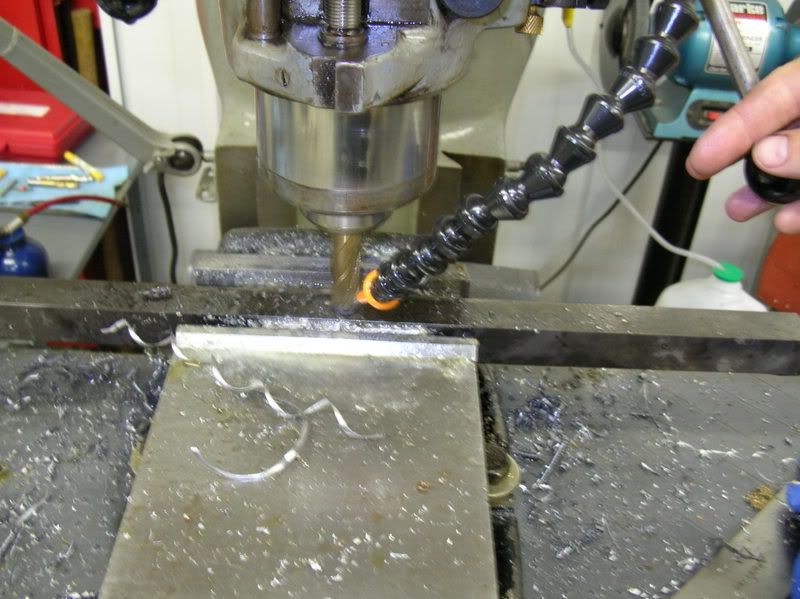
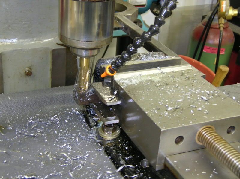
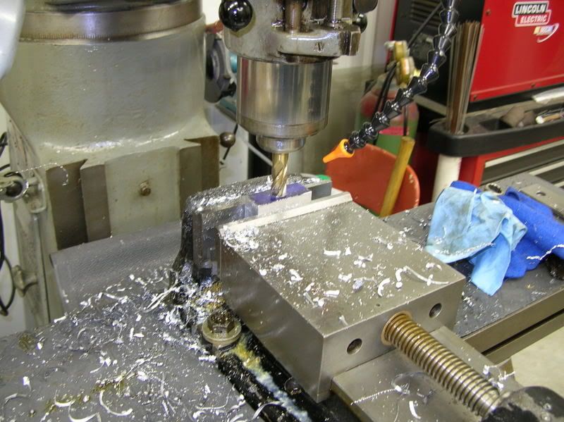
Drill and counter bore frame for idler.
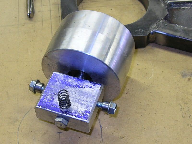
Making block to carry tracking idler. This will hand under the pivot arm and be adjustable with a bolt pushing down on the back.
Finished with idler attached. Your looking at the bottom side, the spring pushes against a plate to keep tension against the adjustment screw. The threaded bushings on the shoulder bolts allow it to pivot.
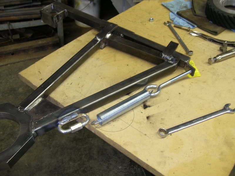
Build bracket to carry idler and to mount belt tension spring.
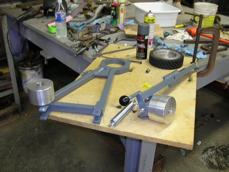
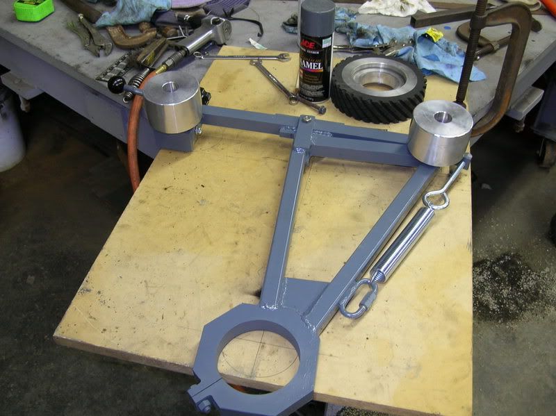
Paint parts and final assemble.
Ready to install.
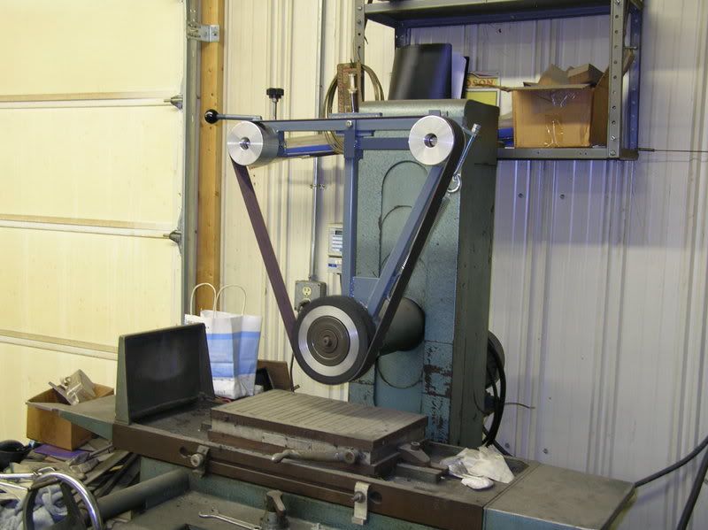
And there you have it.
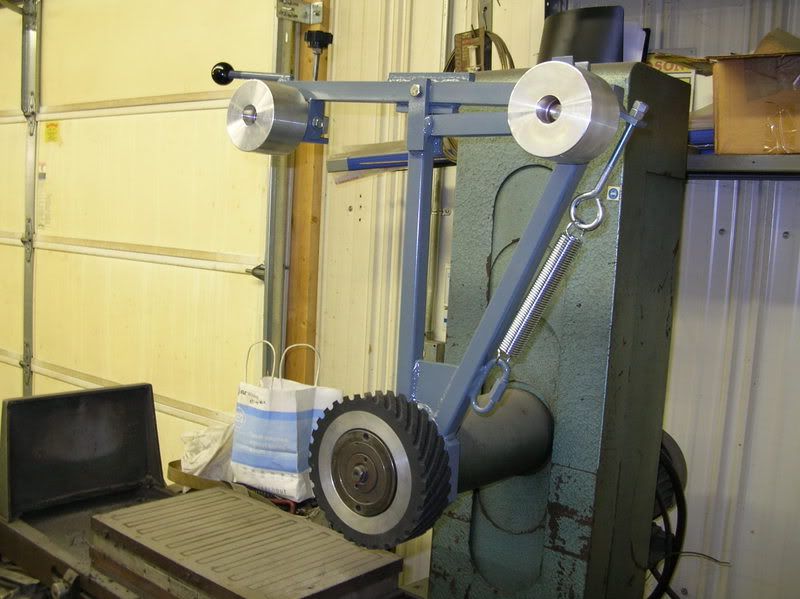
She's off and running.
On my conversions I use a double idler set up that tracks very solid. It consists of a main frame that carries one of the idlers and a spring loaded pivot arm that carries the other idler which is adjustable for tracking. This is much like a KMG or Bader BIII grinder set up.
First of all you need to make a clamp ring that fits the spindle of the machine. This one is milled from one inch thick stock but I have also done this from round stock on a lathe. I make them one inch because I use one inch square stock for the frame.
I had Bader make the contact wheel and idlers for me. This one is an 8x2 90 duro contact wheel. The idlers are crowned 2 1/2 x 3 with a .625 shaft that's threaded to except a 3/8 inch bolt.
An easy way to lay it out is to use a piece of plywood that you can clamp the wheels in place. Take a belt and clamp the wheels where you want them and trace around them and then establish the center of them. From there you can draw on the board and build the frame to hold them in that position.
The clamping ring is in the dead center of the contact wheel and the top piece of the main frame is center of the right idler and will be drilled and counter bored to except the idler.
Its not necessary but it could be helpful to put the frame on the grinder after its built just to double check alignment. In the case of this one I built it so the 2 inch wide contact wheel would be 1/2 inch from the frame so I know the counter bore will need to be drilled to set the 2 1/2 inch idlers 1/4 inch from the frame. This way all the wheels run true.
Next I make the pivot arm.
Drill .625 pivot hole in the pivot arm to allow for bushing.
Make bushing for pivot. You want to be able to tighten pivot bushing so it wont bind but the arm will be ridged. Notice in the upper pic I also have guides on the main frame for the end of the pivot arm to ride in.
Drill and counter bore frame for idler.
Making block to carry tracking idler. This will hand under the pivot arm and be adjustable with a bolt pushing down on the back.
Finished with idler attached. Your looking at the bottom side, the spring pushes against a plate to keep tension against the adjustment screw. The threaded bushings on the shoulder bolts allow it to pivot.
Build bracket to carry idler and to mount belt tension spring.
Paint parts and final assemble.
Ready to install.
And there you have it.
She's off and running.
Last edited:
 .
.