Centering Rotary Table for Milling Machine

JRB Blades

Well-Known Member
I am waiting to get my milling machine (3 weeks UGH!). In the meantime I am stockpiling the stuff I need to make some linerlock/frame lock knives and designing folders on draftsight. I have made my first liner lock and now am hooked! I bought a rotary table for my milling machine and bought a 6"x6" piece of precision ground aluminum and will bolt this to the top of my rotary table. To center my rotary table, I know I am supposed to use a dial indicator, but my rotary table has a MT2 hole in the center. I bought a lathe dead center with a MT2 taper on one end and a 3/4 shaft on the other. I was planning on putting the MT into the rotary table and a 3/4" collet in my mill and center it that way. As far as centering the piece of aluminum, I will drill a #15 hole in the center of it, ream it to a 3/16" (same as my pivot). Then using a precision drill rod in my collet, I'll center the aluminum plate (if it isn't already centered from the arbor trick). This way I can get exact measurements with the DRO to get my stop pin track milled out. I'll put a pivot through my liner and into the reamed hole in the aluminum and clamp the liner down and mill the track with a 9/64" end mill so that the track is . 015 thicker than my 1/8" stop pin, giving my .0075 on each side of the stop pin while it's moving in the track.

I hope this makes sense to yall, if you see any area for improvement or if this is a horrible idea, please let me know.

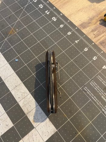
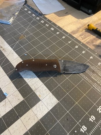
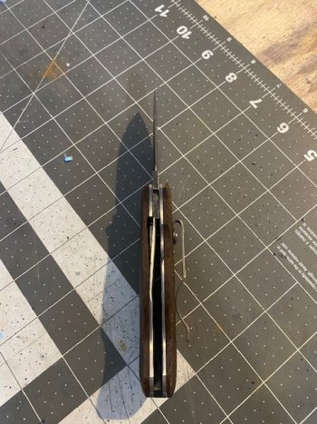
Pics of my first liner lock included...
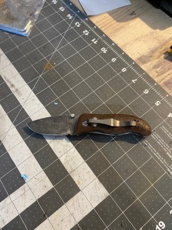
LL3.jpgLL4.jpg

LL1.jpgLL2.jpg
 
I’m not a machinist and I don’t play one on TV. But your idea works. You’ll have to sneak up on your location holes a few times until you can lower the piece of rod / pin into the locating hole without dragging one side. I rotate the spindle by hand once I think I’m there to make sure. Then when you’re happy, lock down the cross slide and set zero on your DRO (if that’s your 0,0,0 position).
 
Just make sure you are accounting for backlash in your table crossfeed travel.
I use a centerpoint in the spindle (chuck or collet), and position the cone of the point down into the hole while moving the table to eliminate any gaps. That will get a fairly close alignment.
 
it does not matter if a hole is tapered.(like the MT bore) it will be ground perpendicular to the bottom of the rotary table. so any point you swing an indicator in that bore will be true without showing any false elliptical path. another thing for visual is generally using a "to size" endmill for a slot gives you a good finish on one wall and a crappy one on the other...because the cutter is essentially climb milling on one side vs conventional on the other.

Typically you would use a 1/8 endmill and cut on center to clear out material.then at one end of the cut you would lift your cutter and move to the final spot you would end up at on the final cut taking out the backlash for the direction the next cut would be in of course. then raise the table so the cutter is in the slot again and dial your x or y axis in or out till you are at the opposite finish wall dimension. lightly lock the axis you were just moving. Then you would unlock and dial your rotary table to the other end of the slot and and lightly lock the rotary table. take out the backlash in the x or y axis screw while it is locked. then un-lock the axis screw and dial the axis the other direction in x or y to get to the finish spot on the second curved wall. then lightly lock the axis table lock. take out any backlash in the rotary table. do this by feel as you probably don't have a rotary DRO. when the handle gets snug you've taken the slop out of the screw( on a new machine might only be a few thousandths)...do this gently or it will want to feed a bit when you unlock it because of the pressure you just added. then unlock your rotary table and dial it to the other end of the slot. and you are finished.

On a manual mill you want to conventional cut to limit chatter from the backlash in the screw. (unless you ordered it with ball-screws). a good rule of thumb is to lightly lock any axis you are not using. On a manual mill you can climb cut on light cuts...some folks will clamp the axis they are moving very lightly so they can turn the dial and not have the mill grab because of the backlash.

a small piece of brass makes for a good trial run to get the hang of milling a slot.

Have fun with the new mill!
 
Thanks for all the tips! I plan on using a 9/64 end mill to mill the stop pin track. I have the exact measurement from the center of my pivot to the center of the stop pin locations. I figured I will just center the rotary table, clamp the blade with a pivot through the blade and into the reamed hole in my aluminum plate. From there, using the DRO I will move the X axis the exact distance to the center of my stop pin location and then make several passes with the end mill to mill out the track.
 
So I saw Chris Crawford's video on his rotary table. He basically has the same setup as me. An aluminum plate mounted to the T slots in the rotary table. To center his aluminum plate, he didn't bother with centering the mill, he was just concerned with centering the hole he had in/near the center of the aluminum plate. I'm thinking that is what I need to do as well.

I got a precision ground 3/16" rod. I insert that into my collet and then loosely attach the aluminum plate to the rotary table, leaving enough slack to be able to move the aluminum plate around a bit. I lower the head down until the collet is almost touching the plate and the precision ground rod is inserted deep in the reamed 3/16" hole in my aluminum plate. I then rotate my table 360 degrees and that sort of self centers the aluminum plate. I then life the head to where the precision ground rod is hovering right above the hole in the aluminum plate and rotate the table 180 degrees and it seems lined up still.

I should be good to go with this method to mill my stop pin track correct?
 
Mount your dial indicator to the mill spindle...so you can swing it in a circle.(an indicol style indicator holder works well...)You indicate the center bore on the rotary table moving the x and y axis until the dial indicator reads "zero" (when you swing it around the bore in the rotary.) that center bore is designed to be true to the travel on that axis. when you swing the indicator on the bore and keep adjusting x,y until the rotary axis center bore is in line with the mill spindle.... you set your x,y dials (or dig. readouts to zero) then you move off the amount you want for the rad you want to cut....

This is how EVERY shop indicates a rotary table into position...
 
Last edited:
Mount your dial indicator to the mill spindle...so you can swing it in a circle.(an indicol style indicator holder works well...)You indicate the center bore on the rotary table moving the x and y axis until the dial indicator reads "zero" (when you swing it around the bore in the rotary.) that center bore is designed to be true to the travel on that axis. when you swing the indicator on the bore and keep adjusting x,y until the rotary axis center bore is in line with the mill spindle.... you set your x,y dials (or dig. readouts to zero) then you move off the amount you want for the rad you want to cut....

This is how EVERY shop indicates a rotary table into position...

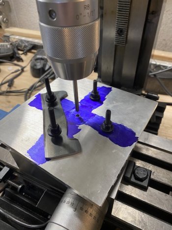
But I have that aluminum plate that will mount over the center hole of my rotary table. I guess I could center the rotary table before mounting the aluminum plate, but if my hole in the aluminum plate is not dead center, it may not work. That is why I was wondering it just centering the hole in the aluminum plate would work?

IMG_7133.jpg
 
Make the hole bigger...sweep the rotary table....or...wonder where your error stacking is coming from.

You HAVE to sweep the rotary table to know where center is anyway. Putting a pin through the plate will center the plate to the spindle....But is your rotary table on center? It has to be on center first!! if the plate is true to the spindle but the rotary table has not been indicated in you will be cutting a cam that will not match the arc you were hoping to cut.


If you have already found center of the rotary table...then yes...using the pin on the plate will work. Getting a nice large hole that you can indicate will be more accurate...and is generally just good shop practice. But if you are tooling off the pin it will work...as long as the rotary table has been accurately centered.
 
Last edited:
I have that hole in the aluminum plate reamed to 3/16" so I can put a 3/16" pivot in my blade and have the blade clamped to the table with the pivot through the blade and into that hole in my aluminum plate, so I can't make that hole bigger. I see what you are saying about centering up my rotary table and then putting on the aluminum plate and centering it to the spindle as well. I think if I center my rotary table and then loosely attach the aluminum plate (after making the mounting holes bigger so I have more wiggle room) with the precision ground rod in my spindle and set down deep into my aluminum plate, I should be able to rotate the table and self center the aluminum plate. Does that sound right?
 
Yes! You got it.

Snub up the pin as short as you can. A little flex can put you off center also. That is not too small a bore to indicate with a test indicator. So, after indicating in your rotary table. Use your pin to center the plate(clamp lightly)...then check the bore with an indicator...turning the spindle slowly...If your plate got snugged down with no flex the indicator should not move much (maybe .0005 max). If it is off more you can lightly tap the plate into zero. Do NOT use the x,y travel to adjust the plate as you will be moving the rotary table off center by doing so. loosen the plate screws (Not sloppy---snug)tap into place, retighten after indicating...and recheck.
 
Perfect! That is what I will do. I have a dial indicator and used it to check my vise.

I'll mount it up and center the rotary table and then do the same with the aluminum plate!

Thanks so much for your help.
 
Back
Top