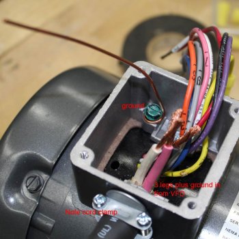
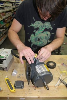
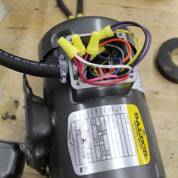
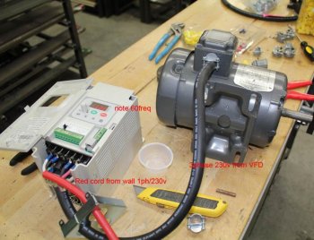
I needed a disc grinder at the warehouse and I didn't want to take mine from my home shop. I had on old VFD I bought on ebay sitting on a shelf for a couple years I bought at a good price and a motor I've had for quite awhile designated for a disc grinder.
Naturally, there was no manual for the VFD. The plate said 230V 3 phase IN/230v 3 phase OUT. What this means is it requires a 3 phase input, which of course I don't have and no one else does either -- unless -- you are in an industrial type set up and you have 3 phase (lucky dog). I've been down this road before. It has been my experience on these VFD's that even if it says 3 phase input required, it will work just fine on 1 phase input. I've wired up 3 of these this way and they all worked. All three were different brands. All three said 3 phase input required. All three worked with 1 phase input. That is why you can often get these pretty cheap on ebay -- no one has 3 phase so they get passed over for the VFD that is documented to say 1/3 phase input - which means it can take 1 or 3 phase input. If you buy a 3 phase and it doesn't work on 1 phase, don't blame me. I just know it worked 3 for 3 for me. You take your own risk here. I'd bet ten bucks this will also work with 110v 1 phase input.
This VFD (variable frequency drive) is a Delta S1 rated for up to 2hp. These speed controllers are technically called drives, not controllers but who cares right? Typically, the higher the horsepower your drive is rated for, the more it will cost. You can get a higher rated VFD, but you should avoid a lower HP rated drive for the motor you are going to run. In other words, a 2hp rated VFD will work on my 1/2hp motor but the other way around, using a 1/2hp rated VFD on a 2hp motor will probably burn it out in short order -- if it will even run.
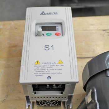
This controller does NOT have a NEMA 4 enclosure. I will have to use compressed air to blow out the metal dust frequently to avoid shorting it out. I've lost two of these to metal dust shorting them out and I was blowing them out often. When you blow the dust out, a certain amount of metal dust fuses to circuits and eventually shorts out the unit. They aren't worth repairing so you are just out. A NEMA 4 enclosure adds about a $75 to $150 to the cost of a VFD and keeps out dust and water. It is worth the price. I won't buy another controller with out it (unless it is stupidly cheap).
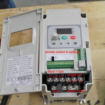
This one is typical of the others. Somewhere on the bottom or back you will find several terminals. This unit did not have a manual so I had to go online and find a manual that was close to this model. The manuals online didn't match so I had to take a guess. You can see what I guessed at (it worked so I guessed right).
Generally, these all have a ground terminal, 3 input and 3 output terminals. Some have additional terminals like this one for a brake resister and external controller of some type. A brake resister is for slowing down a machine quickly when it is turned off. This is important in an larger shop when a tool is turned off and the operator steps away before the machine idles down to a complete stop. If someone else comes along with the machine still spinning, it can be dangerous. A brake resister (almost always an optional add on for additional cost) slows the machine to a dead stop with in 2 seconds. I never use them but you might want to.
Most of these VFD will have several other terminals for remote control operation, sensors and adjustments to various potentiometers to adjust the operation to a specific need. An example would be a motor that needs to be spun up a certain rate. You can program it for that. There are hundreds of combinations of settings on these things. It makes for horrible reading. I have learned to not read any of it. I just run them out of the box. You might want to read your entire manual at least once. Anyway, there is no manual for this one so that makes it a lot easier. Seriously.
Naturally, there was no manual for the VFD. The plate said 230V 3 phase IN/230v 3 phase OUT. What this means is it requires a 3 phase input, which of course I don't have and no one else does either -- unless -- you are in an industrial type set up and you have 3 phase (lucky dog). I've been down this road before. It has been my experience on these VFD's that even if it says 3 phase input required, it will work just fine on 1 phase input. I've wired up 3 of these this way and they all worked. All three were different brands. All three said 3 phase input required. All three worked with 1 phase input. That is why you can often get these pretty cheap on ebay -- no one has 3 phase so they get passed over for the VFD that is documented to say 1/3 phase input - which means it can take 1 or 3 phase input. If you buy a 3 phase and it doesn't work on 1 phase, don't blame me. I just know it worked 3 for 3 for me. You take your own risk here. I'd bet ten bucks this will also work with 110v 1 phase input.
This VFD (variable frequency drive) is a Delta S1 rated for up to 2hp. These speed controllers are technically called drives, not controllers but who cares right? Typically, the higher the horsepower your drive is rated for, the more it will cost. You can get a higher rated VFD, but you should avoid a lower HP rated drive for the motor you are going to run. In other words, a 2hp rated VFD will work on my 1/2hp motor but the other way around, using a 1/2hp rated VFD on a 2hp motor will probably burn it out in short order -- if it will even run.

This controller does NOT have a NEMA 4 enclosure. I will have to use compressed air to blow out the metal dust frequently to avoid shorting it out. I've lost two of these to metal dust shorting them out and I was blowing them out often. When you blow the dust out, a certain amount of metal dust fuses to circuits and eventually shorts out the unit. They aren't worth repairing so you are just out. A NEMA 4 enclosure adds about a $75 to $150 to the cost of a VFD and keeps out dust and water. It is worth the price. I won't buy another controller with out it (unless it is stupidly cheap).

This one is typical of the others. Somewhere on the bottom or back you will find several terminals. This unit did not have a manual so I had to go online and find a manual that was close to this model. The manuals online didn't match so I had to take a guess. You can see what I guessed at (it worked so I guessed right).
Generally, these all have a ground terminal, 3 input and 3 output terminals. Some have additional terminals like this one for a brake resister and external controller of some type. A brake resister is for slowing down a machine quickly when it is turned off. This is important in an larger shop when a tool is turned off and the operator steps away before the machine idles down to a complete stop. If someone else comes along with the machine still spinning, it can be dangerous. A brake resister (almost always an optional add on for additional cost) slows the machine to a dead stop with in 2 seconds. I never use them but you might want to.
Most of these VFD will have several other terminals for remote control operation, sensors and adjustments to various potentiometers to adjust the operation to a specific need. An example would be a motor that needs to be spun up a certain rate. You can program it for that. There are hundreds of combinations of settings on these things. It makes for horrible reading. I have learned to not read any of it. I just run them out of the box. You might want to read your entire manual at least once. Anyway, there is no manual for this one so that makes it a lot easier. Seriously.
Last edited:

