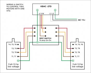
VFD switch wiring... please check my work

jspake

Well-Known Member
hi folks,

i am moving into my new shop (garage at home beats paying for shop space!) and in anticipation of buying a 2nd grinder in the near future, i decided to build a switch to go between two grinders on my KBAC-27D VFD. i have been using this VFD with a 3ph 1.5 hp motor, running it with low voltage 115 wiring with great success on my KMG with for a few years. i purchased a new motor with identical specs to be used on the new grinder. last night i finished building the switch, thanks to many threads i have found on the subject on the various message boards. i checked and double checked everything, and then ran a test.

POOF. a pop. it took me longer than i'd like to admit before i figured out that it was my GFCI that blew, and not my VFD, etc... i then did some research to discover that these VFDs do not work on a GFCI circuit. so tonight i was about to go down and swap the 1st and 2nd outlets, so i could run my grinders on an outlet between the breaker and the GFCI, subsequently being moved to the 2nd position in the circuit... and then i realized something important.

i'm still not 100% sure that my wiring is correct, and it REALLY COULD BE that the GFCI is tripping and actually protecting me because of an error that i have made. i guess this thought materialized because i expected that when i ran my disc grinder, which is controlled by a KBAC-24 it did NOT trip the GFCI, and i'd read that it would. i know very little about this sort of thing, and what i do "know" has been gleaned from online sources, aka you guys. i drew up my wiring scheme and posted it to this message. if some of you know a bit about this, would you mind taking a look at what i've got, and see if it looks legit?
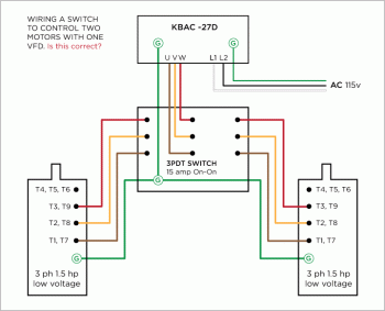
VFD_SWITCH.gif
 
Last edited:
The simplest way to run two motors off one VFD is to go to the hardware store and get two 4 prong outlets (I think that they are electric range outlets and are designed for 230v) and one 4 prong plug. Put the plug on the cord from the VFD and one outlet on each motor. Then you can plug into which ever motor you are going to run. I have this set up on my disk grinder, drill press and mill/drill.

Let me know if I can help you.
 
Your diagram looks ok to me, but it could still be several things causing you problems. First thing that comes to my mind is that VFD's are inherently noisy, electrically noisy. The switching transistors inside put all kinds electrical junk back on the line and I suspect that's what tripping the GFCI. Sometimes, if the motor wiring is bundled with the input power wiring, it'll pick up junk on the line.

Then other things it might be is just a bad GFCI or ground. I've had a GFCI go bad for no apparent reason, tripped no matter what I did. You could also have a less than perfect ground either on the circuit or even the building. Grounds cause as many problems as anything, IMO.

On your test, what were you doing when it tripped? Just pressed start? Flipping the switch? Powering up? etc.
 
I'm with Anthony.

the drawing looks okay. GFCI circuits are notoriously temperamental. A GFCI is looking for current on the ground lead, but keep in mind that the neutral is connected to ground at the breaker box. As Anthony said, VFDs generate a lot of electrical noise (magnetic field) and will cause inductive current on the ground wire. The ground wire is connected to the VFD chassis, and then to the ground wire in your supply side wiring.

My suggestion is to find a different supply circuit with no GFCI devices on it.

Double check that the switch is a "break-before-make". It needs to totally disconnect from Motor A before making contact with Motor B.


Sent from my iPhone using Tapatalk
 
i do as Wayne suggests. Each motor has a male 4-prong plug. The VFD output is a female 4-prong plug. It doesn't get any simpler than that.


Sent from my iPhone using Tapatalk
 
thanks for the feedback, everyone. this is all very helpful.

i know that i can run the VFD with a female 4-prong plug on the output and manually swap plugs out, but i wanted to build a switch box to keep things tidy, and simpler. simple, eventually, i guess.

the info i have on these VFDs not working on e GFCI outlet comes largely from this thread on knifedogs:
http://knifedogs.com/showthread.php...e-Frequncy-Drive-in-a-garage-with-GFI-outlets

i have no reason to think that the GFCI outlet is bad. it tests, and everything else seems to be fine. i've been running a small compressor on this circuit with no problems. it is a brand new building that passed inspection just a couple of months ago. local codes require all garages to have GFCI outlets at the first slot of all circuits. i called KB this morning, as i have read that they have a software update available for this unit, which allows it to function on a GFCI. apparently this is not an upgrade, so much as a new model, which you can purchase... not going to happen. but for those of you who are interested, if you get the KBAC-27D get one with part number 9667 revision G, and it is supposed to work on a GFCI. something else that i was told is that this unit draws 25 amps when run at 115v, so make sure my wiring could handle that. this spooked me a little, with so many reports of shop fires recently. the last thing i want is wires burning up inside the walls. anyone heard of this happening?
 
I agree with your desire to use a switch instead of pigtails- it's a much more elegant and professional way to do things.

As far as the unit drawing 25 amps, what they may be talking about is "in-rush current." When a VFD initiates output to a motor, you can draw up to 6x the nameplate amps. Of course this depends on the load, which is tiny for a grinder. (There is effectively zero load on startup, aside from the friction of the belt which is insignificant.) Still, for fractions of a second the motor will draw higher than normal amperage as the magnetic field builds up enough torque to get the motor spinning. As the motor begins spinning those amps will drop off to nameplate data. For that reason, it is normal to run a VFD on a circuit that is rated for higher amps than the motor's nameplate.

Circuit breakers can withstand current overloads without tripping. This functionality is built into circuit breakers. The trip of a circuit breaker is based on amps x time. Typically the duration of the over-current condition is not nearly long enough to trip the breaker. However, the GFCI circuit may not be nearly as robust. GFCIs are very weak by design since they are meant to be lifesaving devices. .1 amp x 1 second can kill you, so having a long delay in the trip would negate the value of the GFCI.

When I first set up my original shop, I ran a cord from my grinder in the garage into the house and plugged it into the outlet for the dryer. I was renting, so I didn't want to go messing around with the circuits. This setup worked great, except it was sometimes a pain to plug/unplug the dryer when I wanted to make knives. Still, it worked great.

If your circuit breaker box is in the garage, adding another breaker for a dedicated grinder circuit really is pretty simple, assuming you have room for another breaker.
 
Local codes are there for your safety. NEC is the standard. Authority Having Jurisdiction can require more than NEC. If you own the property and the building, you're not breaking any laws by doing away with the GFCI. Adding a dedicated circuit would be your best bet if you intend on running on 115V. Pulling new wiring in the existing conduit is simple enough if the space is available. Your wiring is correct. The GFCI is the problem. They aren't designed for motor loads. John is correct.

I'm a licensed Master Electrician by trade. I am willing to help out if you have any more questions or concerns

Sent from my SM-G920P using Tapatalk
 
john wilson: that's good info regarding the 25 amps issue. i am an amateur at best with these things. the VFD nameplate lists it as 5.5A at 115vac, and my motor lists the FLA as 5.5/2.25. i found the spec sheet online (http://www.techtopind.com/motors/455.pdf) and it lists some other specs about performance, but i'm not at all sure if they are telling me what i think they are. the "starting torque" is listed at 25.55 amps, which may correlate to what you are talking about above. i have a 200 amp sub panel running from the house to this new garage. i have four 220 outlets, and 4 regular 110 circuits, however, as a garage these were required to have GFCI sockets. if this were another type of structure, i do not believe this would have been the case. however, the breaker box is currently full, so adding a dedicated circuit for the grinder isn't an option. and if it were, legally speaking, the circuit would "have to be" a GFCI. this is why i am considering putting a standard socket in the #1 slot, and moving the GFCI to the #2 slot. this would allow me to run the grinder from outlet #1, and everything else would still be covered by the GFCI.

chris taylor: thanks for adding your thoughts. it is good to have a proper electrician to chime in, i really appreciate it. given the starting load issue mentioned above, would the current spike upon startup concern you if you were running this system with 15 or even 20 amp wiring in the walls?
 
Last edited:
My name Chris. Not John. The FLC namplate rating you listed has 2 numbers. The higher number is wired at 230V 3 phase. The lower number is wired for 480V. The higher the voltage the less the amperage. Your full load current is 5.5 at 230V 3 phase. 5.5 amps is what the motor will pull while while running. Your 1.5 hp motor will safely run on a 20A circuit with no problems. Your shop wiring should be 12 AWG on a 20 A circuit. More than enough for this load. The start up will pull more than 5.5 Amp for a fraction of a second. This is normal. Wiring for motors is sized 125%. Circuit breaker are sized at 250%. Per NEC.

You're well within the boundaries. As far as legally speaking. You are wrong. You can legally run your equipment without a GFCI. I can find the articles in the National Electric Code book if you insist on questioning my knowledge on the subject. I'm just saying. I've been in the code for 18 years. I was an electrical instructor for years and I'm confident in my statement. No disrespect. Just professional experience

Sent from my SM-G920P using Tapatalk
 
chris, sorry for the name confusion, that is totally my bad. i corrected it above. thanks for the detailed info on the nameplate data. i fully accept your knowledge of the electrical code, no article necessary :biggrin:. no disrespect taken. you have just the type of expertise i was hoping to find here to alert me of dangers, or put my mind at ease. i'm really only concerned with determining the safety of what i'm trying to do, not the legality anyway. this has been tremendously helpful, thank you very much!
 
Awesome. Glad I didn't come off as a bunghole. One thing I have noticed. The way people perceive you can be different than face to face. I'm glad I was able to help out

Sent from my SM-G920P using Tapatalk
 
no worries at all. besides, I tend to be open to any feedback, regardless of tone, when it could potentially save my life!
 
All of the VFDs that I supply have the GFCI filter. I started specifying that when they came out with the fix.

I think that the plug and outlets is simpler and if at sometime you want to add another piece of equipment it is also simple to do.

Let me know if I can help.
 
hi wayne, i think you are absolutely correct about the "pigtail" style being better suited for growing your VFD versatility. i wanted the switch box because i am likely to be going back and forth between two machines frequently and did not want to have to wrestle cords constantly. anyway, do you know how long KB have been offering the GFCI filter for that unit? i think i picked mine up about 4 years ago. it is a (9536J) as opposed to a (9667G). i think i've got a work around figured out anyway.
 
FYI, I swapped the outlets and plugged in my newly wired switch. everything is working just fine. thanks to all who helped!
 
Jeremy, I think that they were offering both about that time. I did the same swap out of the GFCI plug on mine. The only problem with that is that I can only run my grinder on that circuit.

Let me know if I can help you.
 
FYI, I swapped the outlets and plugged in my newly wired switch. everything is working just fine. thanks to all who helped!

that's great news. I'm glad it worked out and your workaround will be very helpful to anyone else who finds this thread down the road.


Sent from my iPhone using Tapatalk
 
I'm a bit late to the party but, FWIW.
I ran a second line without GFI in my garage and put a couple outlets up in the rafters. I use cord drops for my grinder, table saw, welder, etc...
Everything down at bench level is protected with GFI.
I thought about using twist lock plugs on all my bigger equipment and having the outlets lower but it was cost prohibitive at the time.

I have dropped an extension cord in a puddle when cleaning the car and done a few other stupid things to trip the GFI and wanted to make that non-protected circuit a bit harder to get to so it doesn't accidentally get plugged into. Having two teen boys as adventures(stupid) as me always has me thinking twice about safety in the shop.
 
speaking of folks finding this thread on down the line... after i got it all working i realized that the motors were running backwards... so, if anyone in the future is using the image attached above... don't! i had to swap the wires going to V and W. this one is what got me going in the right direction.

VFD_SWITCH.jpg
 
Back
Top