SameI was thinking on adding another 2x72 to my shop. I love to weld so I am really looking at this option.
You are using an out of date browser. It may not display this or other websites correctly.
You should upgrade or use an alternative browser.
You should upgrade or use an alternative browser.
U Weld 2x72 Grinder kit support thread
- Thread starter BossDog
- Start date
We need to add an option for a spring tension arm so there will be 3 choices, wire spring, gas spring and pnuematic cylinder.
It should go about here I think.

I added a retainer spring "hump" just under the tracking mech.
I also welded a 1" bolt to the top of the tool bar cage to hold in there. I welded the bolt on head down, threads up . This could just as easy be a piece of round bar I suppose but the bolt was handy.
NOTE: These bolts are all dipped in zinc. Don't breathe in the fumes when you weld these. I am used to just holding my breath as the weld time is just seconds. Most welders know this but it's a good reminder anyway.
After I welded the bolt, I welded a washer onto the bolt. The washer was zinc and just basically melted. I'll have to watch for this in the future.
I don't like a compression spring for tension as they tend to wobble/vibrate more than other methods but they are pretty cheap so now it's an option. If I can locate the "just right" gas spring, it shouldn't be much more than a wire spring.


The star wheels are pretty simple. The 1/2" bolt with 3/4" bolt head fits into the star and you run a bead around it. I wrapped the threads with blue tape to keep any splatter out of the threads. I was welding these on the outside but inside is better I think.
The edges on these can stand a little rounding over.
Your first task when you get your grinder running it to use a slack belt and break all the edges down.

It should go about here I think.
I added a retainer spring "hump" just under the tracking mech.
I also welded a 1" bolt to the top of the tool bar cage to hold in there. I welded the bolt on head down, threads up . This could just as easy be a piece of round bar I suppose but the bolt was handy.
NOTE: These bolts are all dipped in zinc. Don't breathe in the fumes when you weld these. I am used to just holding my breath as the weld time is just seconds. Most welders know this but it's a good reminder anyway.
After I welded the bolt, I welded a washer onto the bolt. The washer was zinc and just basically melted. I'll have to watch for this in the future.
I don't like a compression spring for tension as they tend to wobble/vibrate more than other methods but they are pretty cheap so now it's an option. If I can locate the "just right" gas spring, it shouldn't be much more than a wire spring.
The star wheels are pretty simple. The 1/2" bolt with 3/4" bolt head fits into the star and you run a bead around it. I wrapped the threads with blue tape to keep any splatter out of the threads. I was welding these on the outside but inside is better I think.
The edges on these can stand a little rounding over.
Your first task when you get your grinder running it to use a slack belt and break all the edges down.
Last edited:
Justin Wells
Member
Very Cool!
There are strong opinions on what method should provide belt tension.
There are basically 4 methods for this.
The cheapest option is a wire spring of course. A spring vibrates and wiggles a bit. This is almost never a problem but grinder builders like to point that out. Let's say this option is $15. (just spit balling numbers here for an example)
The next option would be a gas spring. Fairly cheap and they are a bit more stable and vibrate a bit less than a wire spring. Let's call this option $30.
and the third choice is My hands down favorite, is the pneumatic gas spring. This option is a bit pricey as you need an air pressure regulator, a pneumatic cylinder that will handle up to 120psi, a safety release valve, some hose and fitting to plumb it all together. I will have to research pricing on this a bit but we'll say it's around $150.
For the pneumatic setup I used Harbor Fright for the regulator and fittings and that is about as cheap as you can find it. The safety release valve is rare and costs more than it should for what it does.
A gas spring set up. The tension is significant with the 50lb strut. The forward connecting points give the assembly some additional stability.

The wire spring is the cheapest way to go. It works. I do need a method hold the spring in place if you tip it sideways. I think a small cotter pin through the lug on the tension arm should work.

Finally, the pneumatic spring allows you to adjust the tension up to the point of breaking belts. I run it around 45-50PSI.
The downside is it is 10 times the cost of a wire spring and requires a compressor to be running or the tank at least charged. This set up consumes almost no air from your compressor.
The upside is it works very well and it's fast.


There are basically 4 methods for this.
- a compression wire spring
- a extension (pull) spring on the back of the tension arm. I used this method on the No Weld Grinder. It works and a cheap door spring does it.
- a gas strut
- a pneumatic set up
The cheapest option is a wire spring of course. A spring vibrates and wiggles a bit. This is almost never a problem but grinder builders like to point that out. Let's say this option is $15. (just spit balling numbers here for an example)
The next option would be a gas spring. Fairly cheap and they are a bit more stable and vibrate a bit less than a wire spring. Let's call this option $30.
and the third choice is My hands down favorite, is the pneumatic gas spring. This option is a bit pricey as you need an air pressure regulator, a pneumatic cylinder that will handle up to 120psi, a safety release valve, some hose and fitting to plumb it all together. I will have to research pricing on this a bit but we'll say it's around $150.
For the pneumatic setup I used Harbor Fright for the regulator and fittings and that is about as cheap as you can find it. The safety release valve is rare and costs more than it should for what it does.
A safety release valve when opened, flows air (or gas) through like normal. When closed (air flow shut off) a small vent opens to allow pressurized air to bleed out letting the gas cylinder deflate.
A regular ball valve will work. You will need to wait a few seconds for the air pressure to bleed off however.
A gas spring set up. The tension is significant with the 50lb strut. The forward connecting points give the assembly some additional stability.
The wire spring is the cheapest way to go. It works. I do need a method hold the spring in place if you tip it sideways. I think a small cotter pin through the lug on the tension arm should work.
Finally, the pneumatic spring allows you to adjust the tension up to the point of breaking belts. I run it around 45-50PSI.
The downside is it is 10 times the cost of a wire spring and requires a compressor to be running or the tank at least charged. This set up consumes almost no air from your compressor.
The upside is it works very well and it's fast.
Chris Railey
Well-Known Member
You should have a contest or something where we get to name the creation for you. Something like The Mickley Mauler 2x72...
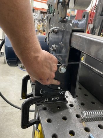
To keep the grinder in the vertical position, it needs to be "pinned" in place. On arc bracket that attaches to the main plate, there is a small hole.
With the grinder to vertical position, drill through this hole with a 1/4" drill bit and then use a 1/4" rod to "pin" the grinder in the vertical position. Remove the pin swivel down to the horizontal position. This has to be done after everything is welded and assembled. I can't design in 2 holes that line up depending on how you weld it together so one of those holes has to be drilled after assembly.
I think this can be improved but it will work for now.
This is the only hole you will have to drill - hopefully.
At least that is the plan.
Attachments
This is taking a couple MONTHS longer than I anticipated. I have lot's of names for it at this point.You should have a contest or something where we get to name the creation for you. Something like The Mickley Mauler 2x72...
The wheels have been bolted on using 1/2" bolts and washers and machinery bushings.
Machinery bushings are just washers with a special shape. These go next to the wheel bearings. The ID fits the 1/2" bolt and the OD is not larger than the bearings pressed into the pockets on the wheels. This means the bushing will not rub on the wheel but the pressure is on the outer rim of the bearing.
Stack 2 of these on either side of the wheel bearing and then add enough washers to line the wheels up

The swivel block side with 2 machinery bushings stacked up.

The motor side with 2 machinery bushings and a fender washer.

When you are lining up the wheels, start with the 4 wheel set up first.
Stack washers on the contact wheels first, then the tracking wheel and finally move the drive wheel in and out on the motor drive shaft to get them lined up. After that, pop in your single contact wheel and stack washers accordingly.
Careful how tight this is. You want the bolt just tight enough to not wobble but any tighter and bind things up. The wheel should spin freely by hand or you have it too tight. We will ship these with locking nuts. I just used regular nuts shown here during prototyping.

Your platen will absolutely require some tweaks to get perfectly lined up. We bend these by hand in a 20 air over hydraulic press brake and they will each be slightly different. Use a hammer to tap these to the shape and bend you need.

Here the tracking wheel shows it needs some additional washers. Keep in mind that occasionally, you will track your belt off the wheels slightly and this might be just right.
The tracking wheel swivels on a 1/4"x3" bolt. Use a washer between the brackets and block.

This is the tracking adjustment block. You can see the 1/4" through hole that is the pivot. You can also see the threaded 1/2"-13 (coarse) hole to hold the tracking wheel. The sharpie circle mark shows where the adjustment screw pushes against the block to swivel the assembly in or out.
Note the top and bottom of the swivel bloc is slightly rounded. We do that to give some additional swivel room. If you still need more swivel room, grind away on the XXX's to allow the block to swivel just a bit further.
While this looks mickey mouse, it works well and it's cheap. Keep that in mind. This is a budget grinder.

Machinery bushings are just washers with a special shape. These go next to the wheel bearings. The ID fits the 1/2" bolt and the OD is not larger than the bearings pressed into the pockets on the wheels. This means the bushing will not rub on the wheel but the pressure is on the outer rim of the bearing.
Stack 2 of these on either side of the wheel bearing and then add enough washers to line the wheels up
The swivel block side with 2 machinery bushings stacked up.
The motor side with 2 machinery bushings and a fender washer.
When you are lining up the wheels, start with the 4 wheel set up first.
Stack washers on the contact wheels first, then the tracking wheel and finally move the drive wheel in and out on the motor drive shaft to get them lined up. After that, pop in your single contact wheel and stack washers accordingly.
Careful how tight this is. You want the bolt just tight enough to not wobble but any tighter and bind things up. The wheel should spin freely by hand or you have it too tight. We will ship these with locking nuts. I just used regular nuts shown here during prototyping.
Your platen will absolutely require some tweaks to get perfectly lined up. We bend these by hand in a 20 air over hydraulic press brake and they will each be slightly different. Use a hammer to tap these to the shape and bend you need.
Here the tracking wheel shows it needs some additional washers. Keep in mind that occasionally, you will track your belt off the wheels slightly and this might be just right.
The tracking wheel swivels on a 1/4"x3" bolt. Use a washer between the brackets and block.
This is the tracking adjustment block. You can see the 1/4" through hole that is the pivot. You can also see the threaded 1/2"-13 (coarse) hole to hold the tracking wheel. The sharpie circle mark shows where the adjustment screw pushes against the block to swivel the assembly in or out.
Note the top and bottom of the swivel bloc is slightly rounded. We do that to give some additional swivel room. If you still need more swivel room, grind away on the XXX's to allow the block to swivel just a bit further.
While this looks mickey mouse, it works well and it's cheap. Keep that in mind. This is a budget grinder.
Lol
Lol I can imagineThis is taking a couple MONTHS longer than I anticipated. I have lot's of names for it at this point.
After a day and half of cutting, I have enough plasma cut parts to assemble 5 grinders.
We are still waiting on wheels and we have to fabricate some brackets and the tension swivel block.
3 of these are spoken for so we will have a couple ready at the end of the week. We do not have pricing yet.
That is scheduled to be determined next Tuesday.

We are still waiting on wheels and we have to fabricate some brackets and the tension swivel block.
3 of these are spoken for so we will have a couple ready at the end of the week. We do not have pricing yet.
That is scheduled to be determined next Tuesday.
Justin Wells
Member
I already messaged you guys on Instagram I’d be very interested to give one a shot aswell
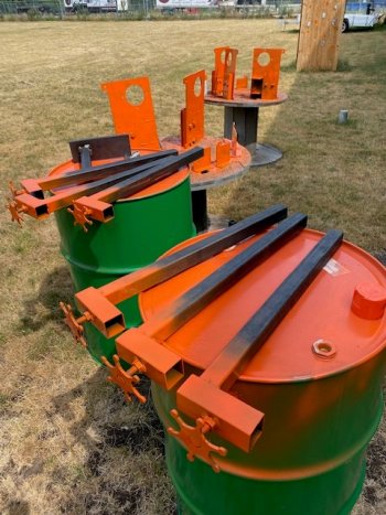
Getting some parts painted on our first batch of 5 beta release grinders.

Here Luke and Alyssa are hard at it working on some of the parts while the CNC plasma cuts a few more.

This CNC plasma table is fun. It's dirty, messy, noisy, smoky fun.

The pile of shame continues to grow.

We are waiting on some more drive and tracking wheels. I don't want to wipe out the stock we have so we wait.
While we are waiting, here is some fish I caught saturday jigging with an ultralight rod and crappie jig. Pike love to bite crappie bait. This one is 27" plus and took about 10 minutes to reel in. Every time he got close to the boat he ran again.

Here Luke and Alyssa are hard at it working on some of the parts while the CNC plasma cuts a few more.
This CNC plasma table is fun. It's dirty, messy, noisy, smoky fun.
The pile of shame continues to grow.
We are waiting on some more drive and tracking wheels. I don't want to wipe out the stock we have so we wait.
While we are waiting, here is some fish I caught saturday jigging with an ultralight rod and crappie jig. Pike love to bite crappie bait. This one is 27" plus and took about 10 minutes to reel in. Every time he got close to the boat he ran again.
Attachments
Water table helps keep the smoke down.Nice day on the lakeGetting some parts painted on our first batch of 5 beta release grinders.
View attachment 78594
Here Luke and Alyssa are hard at it working on some of the parts while the CNC plasma cuts a few more.
View attachment 78595
This CNC plasma table is fun. It's dirty, messy, noisy, smoky fun.
View attachment 78596
The pile of shame continues to grow.
View attachment 78597
We are waiting on some more drive and tracking wheels. I don't want to wipe out the stock we have so we wait.
While we are waiting, here is some fish I caught saturday jigging with an ultralight rod and crappie jig. Pike love to bite crappie bait. This one is 27" plus and took about 10 minutes to reel in. Every time he got close to the boat he ran again.
View attachment 78598

Justin Wells
Member
Do you have a price yet Boss?These should be done tomorrow.
We have started cutting parts for kits to list on the website by the end of next week.
View attachment 78621
I gotta plan out my budget LOL