curtisk
Well-Known Member
B]GIB Mods for Step Pulley Operation[/B]
I put this together for folks wanting to build the “Grinder in a Box”. I gleaned information from posts by Ed Caffrey, Jason Wilder, and other unknown authors, with a few additions of my own (mostly the crappy welding). Feel free to add, move stuff around, or virtually anything you want to do with it except comment on my crappy welding skills. The only thing I ask is that if you make it your own that you give credit to Ed and Jason.
We will assume that you have some basic mechanical and fab skills. I just built two of the GIBs because they are a bargain to say the least.
Start
After bolting or welding the GIB main frame to the baseplate you will need to add an additional
½”x7”x8 ½” to the base. Weld it to the main base plate being mindful that when adding heat such as in welding, stuff is going to warp. Make sure it stays flat and true to the main baseplate.
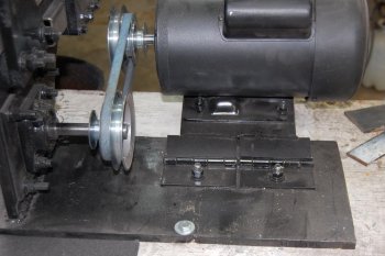
For your motor mount you are going to need two 4” hinges. I got mine from TSC (Tractor Supply Co.). You will also need a piece of 3/16”x7”x8” plate for the motor mount. Bolt sizes are your choice. I mounted the motor assembly measuring 6 ½” from main frame to the hinge. In hind sight, it really needed to be a couple of more inches away from the main frame. It is a bit tight but not hard at all to change the belt speeds.
For the flange bearing mount you will need a piece of ¼”x6”x6”. Just square it and clamp it to the main frame. Make your holes via the holes that Jamie at Polar Bear Forge has jetted into the main frame. You can mark out for flange bearing at the same time or bolt it up to the main frame after drilling. I personally chose the latter method because if it can be screwed up, well…
Drill the holes, FYI, I used 3/8” bolts for the assembly.
If you go the latter route, put a couple of bolts in it and tighten them up. Put the right side (if looking from the front of the grinder) flange bearing inside the motor mounting hole, center it, mark it, and then remove the mounting plate/assembly. Make sure you drill or cut a large enough hole for the drive shaft to go through.
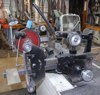
Once you have completed all of that, mount her up again. And the right side should look similar to this.
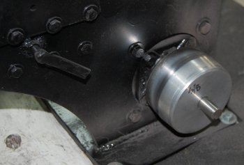
and the left side...
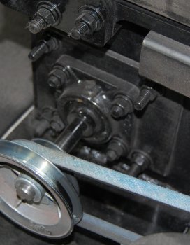
In the photo you will also notice that my work table arm locking bolt is on the right side of the grinder. Putting them both on the same side (such as on the left side) is an experiment in aggravation. You will also see that I welded a nut onto it rather than tap it out. I broke the tap and went this route and it works fine. I used 5/16” bolts for the locks rather than ¼”.
Ed Caffrey suggested tossing the idea of a tension spring and using a compression spring, and I could not agree with him more. Compression is the way to go. Ed also suggested drilling a new hole for the tension/tracking arm and I encourage it as well. You will need a bit more arm and it helps with tracking.
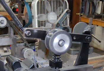
Compression Spring assembly: Lowes sells a set of porch swing springs that are “ginormous” but work perfectly. Best I can recall they were around 10 bucks for a pair. Cut and remove the metal rods from the middle of the spring and you are set to go. Weld a1 ½” piece of 2” OD square tubing to the GIB in a position that is just to the rear of your idler/tracking adjustment. Check it to make sure it is not too close to the idler/tracking assembly. This serves as a cup for the spring and you really do not need a guide for
the top of the spring.
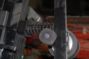
You will also notice that the idler mounting bracket is slotted in the front. Someone else did this and I thought it was a good idea so I added it to the grinders. Also, your idler/tracking screw should be 5/16”. ¼” is too small for rough use.
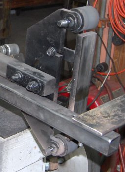
Platen mount: 2 pieces of ¼”x 2 ¼” x 2 ¼” angle iron cut in a 1 1/4” width works well for this. The holes that mount to the platen frame should be 5/16” and the platen mounting bolts can be ¼”. Slot the angle iron for the platen bolts and slot the platen frame. These are handy for making minute adjustments.
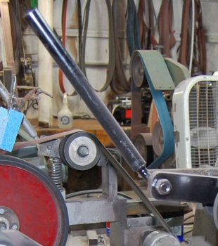
Idler tensioning arm: because you have added a beast of a spring you will have to have a way to pull down on the idler/tensioning arm. I drilled out the handle hole in the arm to ½”. Take a ½” x 3 ½” bolt and grind the head of it down until it slips into a piece of 5/8” ID x 10” pipe. Weld it up and the heat and bend a 90 into it.
These instruction couple with what is already out there on the web should get you up and running. The GIB was designed for a direct motor mount so any mods to it are going to be a bit of a challenge. They are not difficult, just take your time. Regards, Curtis K.
I put this together for folks wanting to build the “Grinder in a Box”. I gleaned information from posts by Ed Caffrey, Jason Wilder, and other unknown authors, with a few additions of my own (mostly the crappy welding). Feel free to add, move stuff around, or virtually anything you want to do with it except comment on my crappy welding skills. The only thing I ask is that if you make it your own that you give credit to Ed and Jason.
We will assume that you have some basic mechanical and fab skills. I just built two of the GIBs because they are a bargain to say the least.
Start
After bolting or welding the GIB main frame to the baseplate you will need to add an additional
½”x7”x8 ½” to the base. Weld it to the main base plate being mindful that when adding heat such as in welding, stuff is going to warp. Make sure it stays flat and true to the main baseplate.

For your motor mount you are going to need two 4” hinges. I got mine from TSC (Tractor Supply Co.). You will also need a piece of 3/16”x7”x8” plate for the motor mount. Bolt sizes are your choice. I mounted the motor assembly measuring 6 ½” from main frame to the hinge. In hind sight, it really needed to be a couple of more inches away from the main frame. It is a bit tight but not hard at all to change the belt speeds.
For the flange bearing mount you will need a piece of ¼”x6”x6”. Just square it and clamp it to the main frame. Make your holes via the holes that Jamie at Polar Bear Forge has jetted into the main frame. You can mark out for flange bearing at the same time or bolt it up to the main frame after drilling. I personally chose the latter method because if it can be screwed up, well…
Drill the holes, FYI, I used 3/8” bolts for the assembly.
If you go the latter route, put a couple of bolts in it and tighten them up. Put the right side (if looking from the front of the grinder) flange bearing inside the motor mounting hole, center it, mark it, and then remove the mounting plate/assembly. Make sure you drill or cut a large enough hole for the drive shaft to go through.
Once you have completed all of that, mount her up again. And the right side should look similar to this.

and the left side...

In the photo you will also notice that my work table arm locking bolt is on the right side of the grinder. Putting them both on the same side (such as on the left side) is an experiment in aggravation. You will also see that I welded a nut onto it rather than tap it out. I broke the tap and went this route and it works fine. I used 5/16” bolts for the locks rather than ¼”.
Ed Caffrey suggested tossing the idea of a tension spring and using a compression spring, and I could not agree with him more. Compression is the way to go. Ed also suggested drilling a new hole for the tension/tracking arm and I encourage it as well. You will need a bit more arm and it helps with tracking.

Compression Spring assembly: Lowes sells a set of porch swing springs that are “ginormous” but work perfectly. Best I can recall they were around 10 bucks for a pair. Cut and remove the metal rods from the middle of the spring and you are set to go. Weld a1 ½” piece of 2” OD square tubing to the GIB in a position that is just to the rear of your idler/tracking adjustment. Check it to make sure it is not too close to the idler/tracking assembly. This serves as a cup for the spring and you really do not need a guide for
the top of the spring.

You will also notice that the idler mounting bracket is slotted in the front. Someone else did this and I thought it was a good idea so I added it to the grinders. Also, your idler/tracking screw should be 5/16”. ¼” is too small for rough use.
Platen mount: 2 pieces of ¼”x 2 ¼” x 2 ¼” angle iron cut in a 1 1/4” width works well for this. The holes that mount to the platen frame should be 5/16” and the platen mounting bolts can be ¼”. Slot the angle iron for the platen bolts and slot the platen frame. These are handy for making minute adjustments.

Idler tensioning arm: because you have added a beast of a spring you will have to have a way to pull down on the idler/tensioning arm. I drilled out the handle hole in the arm to ½”. Take a ½” x 3 ½” bolt and grind the head of it down until it slips into a piece of 5/8” ID x 10” pipe. Weld it up and the heat and bend a 90 into it.

These instruction couple with what is already out there on the web should get you up and running. The GIB was designed for a direct motor mount so any mods to it are going to be a bit of a challenge. They are not difficult, just take your time. Regards, Curtis K.


