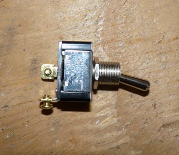
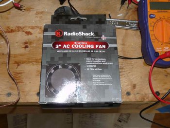
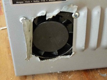
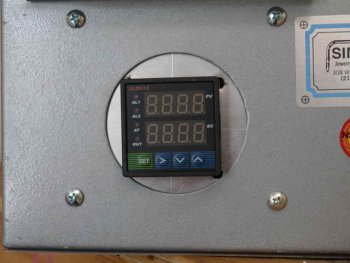
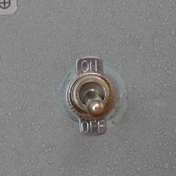
Next I hooked up the toggle switch. It goes on the black wire coming from the power cord on one terminal and the other terminal (the on position) has a wire going from the switch to the number 1 terminal on the PID and also a wire going to the cooling fan.
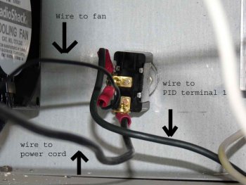
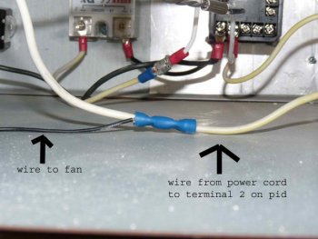
Next I ran the white wire from the power cord to the number 2 terminal of the PID. In the middle of this I put in a splice to hook up the other wire to the cooling fan.
For the solid state relay I drilled holes to mount it but I hooked up the wires before actually mounting it. Did that make since? Same thing for the PID. I hooked all the wires up then mounted it in place.
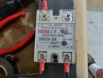
Here is the solid state relay, mounted, with the wires hooked up. Note that it is mounted upside down in this picture.
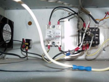
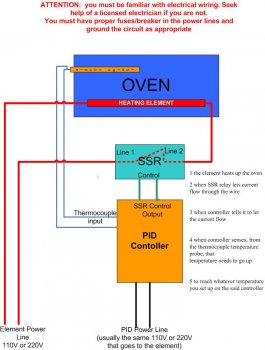
The picture shows ssr terminal 3 connected to PID terminal 6. Ssr terminal 4 to PID terminal 7. Ssr terminal 2 to one heating element wire. Ssr terminal 1 is connected to PID terminal 1. Remember, terminal 1 on the PID is also connected to the toggle switch.
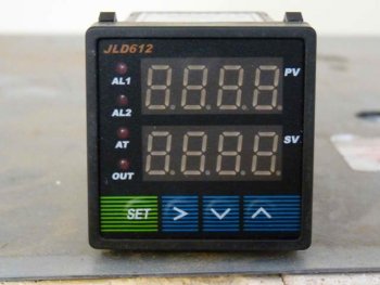
Now here is what's going on with the PID.
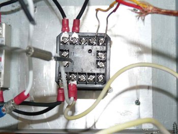
Terminal 1 has wires going to the ssr, terminal 1 and to the toggle switch. terminal 2 has a wire going from the power cord, and another wire going to the other heating element wire. Terminal 6 goes to ssr terminal 3. Terminal 7 goes to ssr terminal 4.
The thermocouple has a yellow and red wire. The yellow wire goes to the 9 terminal and the red goes to the 10 terminal.
And there you go. Get the toggle switch mounted,
Mount the SSR and PID and you are all ready to go!
