Sticks
Well-Known Member
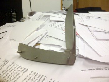
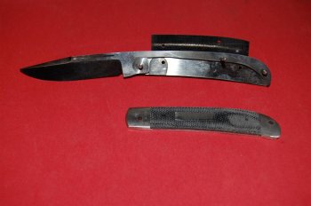
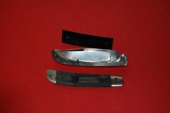
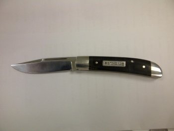
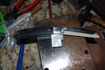
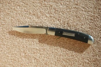
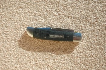
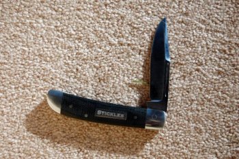
I've only made two slip joints, but this is how I made the knife "Lemony Snicket" posted the other day under the "folding knife" sub-forum. I learned a lot and learned that I have a lot to learn... but anyone interested in making a slipjoint should give it a shot. Nice thing is you doun't use much material, so what's to lose...
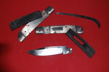
The list of material includes 1/8" thick precision ground steel. I used CPM 154 for the blade and spring; 304 SS for the liners and 303SS for the pin stock and shield and canvas micarta for the scales.
The pivot pin is 1/8" so I used a No. 31 bit and a 1/8" reamer. The other pins are 3/32 so I used a No. 43 bit and 3/32 reamer.
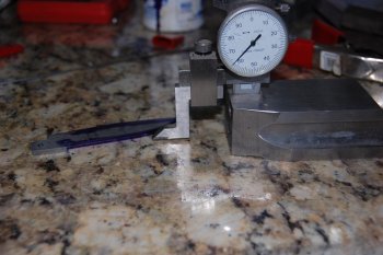
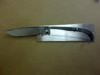
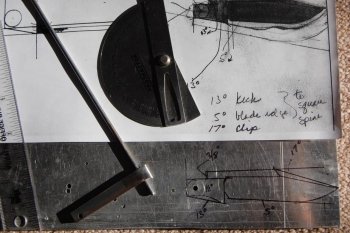
You need a hard flat surface to build a slip joint. One you can drill holes in to test assemble the kinfe, determine spring pressure, etc. I used a piece of hard wood for the first knife, but for this knife I got a 6" x 12" x 1/2" thick plate of aluminum. It works much better and is worth the investment. Other items I wouldn't do without are a steel protractor, caliper, a height guage, slab of granite (I use a sink cut-out) and probably a few other items I'll think of as I type this.
This knife has a half stop. So the key to designing it was to begin with a perfect circle around the pivot hole. (Thank you Bill Vining for your tutorial, in this forum, on How to Build a Texas Toothpick.) I've tried drafting designs on paper with a compass and ruler, but the problem with transferring the design to the steel, for me, is that I've never been able to drill a hole exactly where I wanted to. And so, if the pivot hole is off by just a little bit, the traced design is well... not much help.
So, I decided to drill the pivot hole first and "design" the knife around it, that way I knew the hole was in the correct place. I used precision ground steel which meant that I had a straight edge at the top and end of the steel. I used those as my constants for scribing all lines. To decide where to drill the pivot hole I first had to decide how "deep" as opposed to wide the back spring would be. Somewhere I read that it should be 1 1/2 times the width. So I figured 3/16". I then decided how large I wanted the "circle" around the pivot hole to be. I divided that in half and added the 3/16" and marked that down from the top edge (and gave myself a little extra depth, which proved to be helpful) and about 4" from the end of the steel.
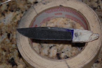
After drilling and reaming the pivot hole, I scribed the circle. The "gizmo" I used is just a lot of masking tape wrapped around 1/8 pin stock with the carbide tip of my scribe.
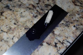
Actually this isn't the circle I ended up using. It was too small, but its the only one I have a picture of at this stage. After I scribed a larger circle, I used a square to scribe a vertical line touching the back of the larger circle and then a line parallel to the top of the larger circle where the spring will be seated.
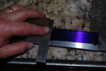
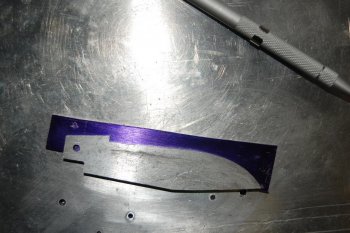
Next I scribed a line at an angle for the kick. In the next picture I have ground the angle for the kick (just touching the circle) and I am measuring the length of the distance of the back of the kick to the parallel line where the back spring will be seated. This measuerment is important to know where to mark the point where the spring will meet the spine of the blade. In other words how long the notch will be.
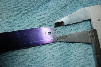
In the next picture I have marked the "notch" for the spring, which should be about 10% longer than the back of the kick.
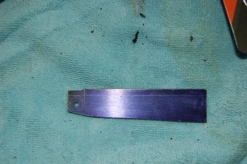
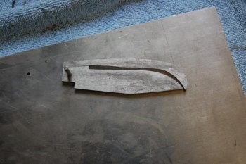
Here I've ground and filed the notch for the spring and have the basic geometry for a half stop slipjoint.
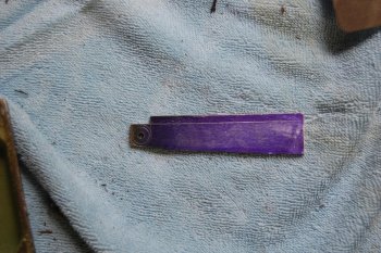
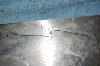
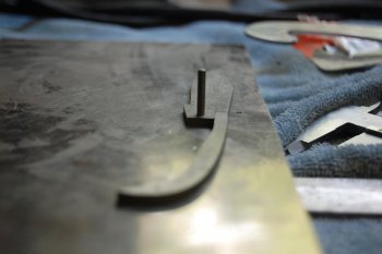
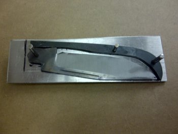
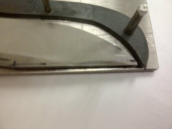
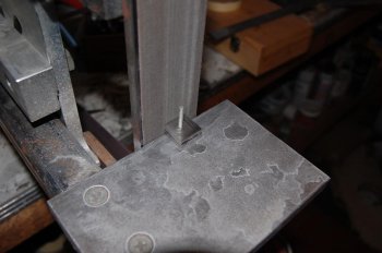
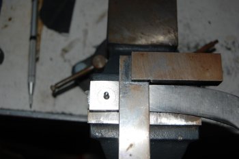
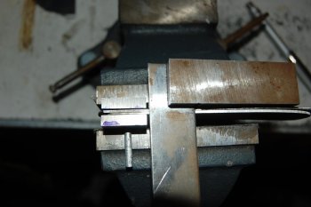
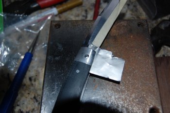
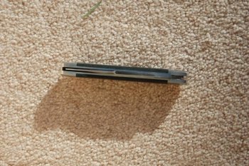
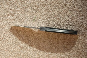
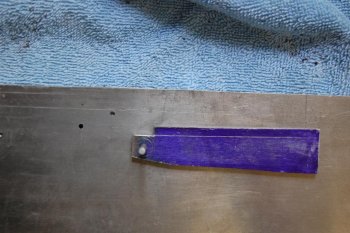
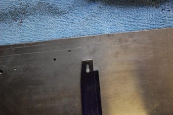
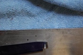
In the next pictures I'm checking to see that the blade will permit the spring to be be flush in the open, half stop and closed position. Really what I'm cecking is to see if the the three surfaces that I ground to the circle are the exact same distance from the center of the pivot hole. I drilled a hole in my aluminum plate. Put the pin stock through the pivot hole and into the plate. I scribed a line along the blade where the spring will sit and rotated the blade making sure that the other two surfaces matched the scribed line This method is simple and I probably should be using a more precise instrument, but it worked for me. The pictures are blurry and I intentionally moved the blade a touch so the scribed line would be visable. And there will always be more fine tuning on final assembly.
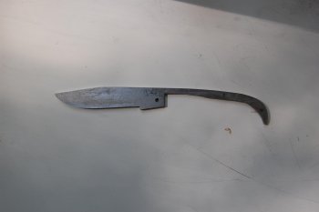
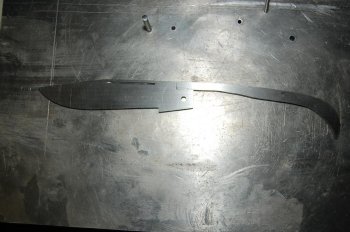
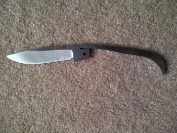
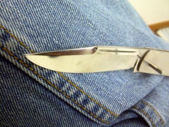
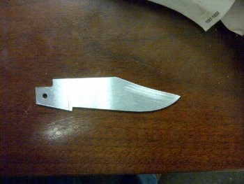
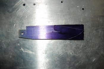
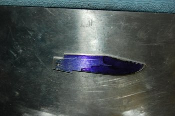
The next two pictures are of the blade design scribed and then the profile ground.
Well, now that the easy part is done, and I can't post anymore pictures on this post, I'll take a break.
Jay
The list of material includes 1/8" thick precision ground steel. I used CPM 154 for the blade and spring; 304 SS for the liners and 303SS for the pin stock and shield and canvas micarta for the scales.
The pivot pin is 1/8" so I used a No. 31 bit and a 1/8" reamer. The other pins are 3/32 so I used a No. 43 bit and 3/32 reamer.
You need a hard flat surface to build a slip joint. One you can drill holes in to test assemble the kinfe, determine spring pressure, etc. I used a piece of hard wood for the first knife, but for this knife I got a 6" x 12" x 1/2" thick plate of aluminum. It works much better and is worth the investment. Other items I wouldn't do without are a steel protractor, caliper, a height guage, slab of granite (I use a sink cut-out) and probably a few other items I'll think of as I type this.
This knife has a half stop. So the key to designing it was to begin with a perfect circle around the pivot hole. (Thank you Bill Vining for your tutorial, in this forum, on How to Build a Texas Toothpick.) I've tried drafting designs on paper with a compass and ruler, but the problem with transferring the design to the steel, for me, is that I've never been able to drill a hole exactly where I wanted to. And so, if the pivot hole is off by just a little bit, the traced design is well... not much help.
So, I decided to drill the pivot hole first and "design" the knife around it, that way I knew the hole was in the correct place. I used precision ground steel which meant that I had a straight edge at the top and end of the steel. I used those as my constants for scribing all lines. To decide where to drill the pivot hole I first had to decide how "deep" as opposed to wide the back spring would be. Somewhere I read that it should be 1 1/2 times the width. So I figured 3/16". I then decided how large I wanted the "circle" around the pivot hole to be. I divided that in half and added the 3/16" and marked that down from the top edge (and gave myself a little extra depth, which proved to be helpful) and about 4" from the end of the steel.
After drilling and reaming the pivot hole, I scribed the circle. The "gizmo" I used is just a lot of masking tape wrapped around 1/8 pin stock with the carbide tip of my scribe.

Actually this isn't the circle I ended up using. It was too small, but its the only one I have a picture of at this stage. After I scribed a larger circle, I used a square to scribe a vertical line touching the back of the larger circle and then a line parallel to the top of the larger circle where the spring will be seated.

Next I scribed a line at an angle for the kick. In the next picture I have ground the angle for the kick (just touching the circle) and I am measuring the length of the distance of the back of the kick to the parallel line where the back spring will be seated. This measuerment is important to know where to mark the point where the spring will meet the spine of the blade. In other words how long the notch will be.

In the next picture I have marked the "notch" for the spring, which should be about 10% longer than the back of the kick.

Here I've ground and filed the notch for the spring and have the basic geometry for a half stop slipjoint.

In the next pictures I'm checking to see that the blade will permit the spring to be be flush in the open, half stop and closed position. Really what I'm cecking is to see if the the three surfaces that I ground to the circle are the exact same distance from the center of the pivot hole. I drilled a hole in my aluminum plate. Put the pin stock through the pivot hole and into the plate. I scribed a line along the blade where the spring will sit and rotated the blade making sure that the other two surfaces matched the scribed line This method is simple and I probably should be using a more precise instrument, but it worked for me. The pictures are blurry and I intentionally moved the blade a touch so the scribed line would be visable. And there will always be more fine tuning on final assembly.


The next two pictures are of the blade design scribed and then the profile ground.


Well, now that the easy part is done, and I can't post anymore pictures on this post, I'll take a break.
Jay
Last edited:

