Well, I got most of this done yesterday! Still have a laundry list of things to finish up, but it's functional!! I used a lot of the info from Dennis Tyrell's build on Youtube.
Step 1: Get your contact wheel lined up with your other wheels on the belt sander so it runs inline. Since I have an AmeriBrade with 2" tubing, I needed an 8" long, 1/2" diameter bolt. I used a 1.5" spacer and 2 1/2" ID washers to get the correct offset, which was around 1.75". The smaller OD of the long spacer worked in place of another smaller washer. I also added another washer under the bolt head on the other side, too. This is a 6" diameter, 90 duro, 2" wide wheel from the big river site, was only $50! So 1/2-13, 8" bolt, lock nut, 3 washers and 1.5" long spacer for these parts, and the 2" square aluminum arm.
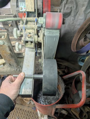
Step 2: Figure out where things need to get drilled! I drilled a 1/2" hole in my 2" tool arm after eyeballing where the sliding table and wheel will overlap. Dennis recommended around 1/4" of overlap; I have a bit more, but that's OK! I picked up a 40" bar of 1/2" thick, 3" wide aluminum to use for the chuck, and the lower plate to connect the sliding table ($85 from big river, this is nice, tight and solid!! I got one of the $35 ones and it totally sucks) to the tool arm. I used a 4" long, 1/2-13 bolt, washers and lock nut to bolt the aluminum connector plate to the tool arm, so the wheel bolt and the 4" long bolt connect the arm to the plate/sliding table. The connecting plate is 12" long; longer than it needs to be, but I have room for adjustment. I drilled the connector plate for 1/4-20 bolts and put washers and nuts onto it.
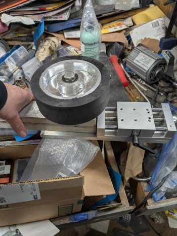
Step 3: I needed to see how the height of the chuck would meet up with the wheel. The wheel was near the top edge of the 3" wide chuck. In retrospect, this was probably OK since I couldn't install the magswitches close to the bottom side of the chuck anyway!
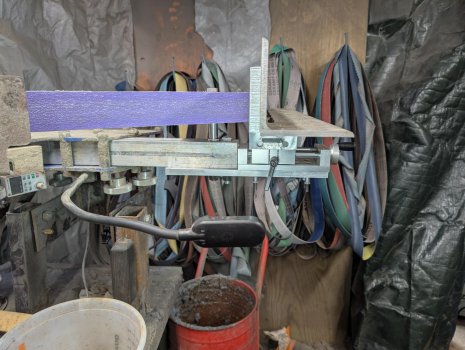
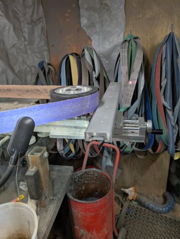
so I at first added some spacers to the sliding table to raise it up, but when I realized that I needed to make an adapter plate for the sliding table and bearing block, I just used 1/2" aluminum for that. Turns out, I probably didn't need the extra height, more on that later!
Step 4: Adapter table plate! So the holes in my linear slide table didn't match with the hole on the chuck and they would be close to the edge or another hole or bearings, so I used a piece of the 1/2" aluminum to make an adapter. Drilled clearance holes and countersunk them to fit the M6 screws to bolt the adapter plate to the liner table, and drilled 4 new clearance holes in the bearing assembly and drilled/tapped for the 1/4-20 screws for the bearing assembly.
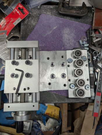
Turns out this made it a bit high and the chuck overlapped the wheel, so I had to add a bunch of spacers to the bolts for the wheel/arm to drop it back down to get the contact wheel more centered on the chuck area. So I probably was OK with the height everything was at before, but still needed to adapt the sliding table to the bearing block.
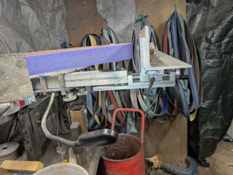
Step 5: Make the chuck! This was a bit complicated. I started with drilling and tapping and bolting a piece of 4" x 4" x 1/4" aluminum angle iron and the 1/2" x3" x 26" piece of aluminum together since that was going to be my chuck. I use 1/4-20 screws for this, 3 of them. I then drilled and attached the bottom leg of the angle iron to the linear rail section to mount the angle iron/aluminum plate to the rail, which slides on the bearing block. M5 screws fit nicely into the rail section, so I drilled the clearance holes and used nuts to secure it instead of drilling and tapping.
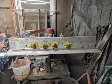
Then I used a carbide tooth 35mm hole saw to make the cuts for the magswitch 150's. First hole went OK (drilling through the 1/4" angle and 1/2" plate at the same time since they are bolted together. I learned I needed to clamp down the piece tightly to my drill press table since the pilot drill bit is useless to make the 2nd hole next to the first one to try to make an oval slot. I got through it, and used my knock off foredom to clean up the holes to the mag switches fit into the openings. There are lots of gaps and it's ugly, but functional! I still have 2 more MagSwitches to install at the farther ends of the chuck. I ended up spacing the first 4 farther apart and I suck at drilling/aligning, so some are at a slight angle. I will do another on each end near the end of the chuck for longer pieces
What it looks like from the side so far:

I didn't even drill/tap the M4 screws to hold the Magswitches to the chuck yet; I plopped them into the holes, put a blade on the other side and turned the switched on. With the blade against the chuck, the magnets stay in place, LOL!
Ugly, but it works!! 80 grit Bora 7 belt on a 64 HRC Magnacut blank:
I still need to dress the chuck so it's square to the wheel, drill the other 2 magswitch cut outs, drill and tap to install the mag switches to the chuck (probably just into the 1/4" angle iron, put stop screws on the bottom leg of the angle iron so I don't dismount the chuck from the bearing block, add a handle and spark deflector. I did the angle/plate for the chuck so I can replace the 1/2" plate as it gets worn. I can also add a spacer between the angle and plate (or between the mag switches and the angle iron to give me more depth to adjust the chuck to the wheel periodically before I need to replace the 1/2" thick chuck.
The tilting you see if from my horribly tilting assembly I built for my AmeriBrade. I was going to cut some angle iron as a 3rd leg to stabilize it, I am just going to buy their tilting assembly instead of redoing mine now that I have the surface grinder! I never used it horizontally before because it was a bit high and was wobbly, but now that I have the SGA going, I am getting the better adapter that will solve both of the problems!
Step 1: Get your contact wheel lined up with your other wheels on the belt sander so it runs inline. Since I have an AmeriBrade with 2" tubing, I needed an 8" long, 1/2" diameter bolt. I used a 1.5" spacer and 2 1/2" ID washers to get the correct offset, which was around 1.75". The smaller OD of the long spacer worked in place of another smaller washer. I also added another washer under the bolt head on the other side, too. This is a 6" diameter, 90 duro, 2" wide wheel from the big river site, was only $50! So 1/2-13, 8" bolt, lock nut, 3 washers and 1.5" long spacer for these parts, and the 2" square aluminum arm.

Step 2: Figure out where things need to get drilled! I drilled a 1/2" hole in my 2" tool arm after eyeballing where the sliding table and wheel will overlap. Dennis recommended around 1/4" of overlap; I have a bit more, but that's OK! I picked up a 40" bar of 1/2" thick, 3" wide aluminum to use for the chuck, and the lower plate to connect the sliding table ($85 from big river, this is nice, tight and solid!! I got one of the $35 ones and it totally sucks) to the tool arm. I used a 4" long, 1/2-13 bolt, washers and lock nut to bolt the aluminum connector plate to the tool arm, so the wheel bolt and the 4" long bolt connect the arm to the plate/sliding table. The connecting plate is 12" long; longer than it needs to be, but I have room for adjustment. I drilled the connector plate for 1/4-20 bolts and put washers and nuts onto it.

Step 3: I needed to see how the height of the chuck would meet up with the wheel. The wheel was near the top edge of the 3" wide chuck. In retrospect, this was probably OK since I couldn't install the magswitches close to the bottom side of the chuck anyway!


so I at first added some spacers to the sliding table to raise it up, but when I realized that I needed to make an adapter plate for the sliding table and bearing block, I just used 1/2" aluminum for that. Turns out, I probably didn't need the extra height, more on that later!
Step 4: Adapter table plate! So the holes in my linear slide table didn't match with the hole on the chuck and they would be close to the edge or another hole or bearings, so I used a piece of the 1/2" aluminum to make an adapter. Drilled clearance holes and countersunk them to fit the M6 screws to bolt the adapter plate to the liner table, and drilled 4 new clearance holes in the bearing assembly and drilled/tapped for the 1/4-20 screws for the bearing assembly.

Turns out this made it a bit high and the chuck overlapped the wheel, so I had to add a bunch of spacers to the bolts for the wheel/arm to drop it back down to get the contact wheel more centered on the chuck area. So I probably was OK with the height everything was at before, but still needed to adapt the sliding table to the bearing block.

Step 5: Make the chuck! This was a bit complicated. I started with drilling and tapping and bolting a piece of 4" x 4" x 1/4" aluminum angle iron and the 1/2" x3" x 26" piece of aluminum together since that was going to be my chuck. I use 1/4-20 screws for this, 3 of them. I then drilled and attached the bottom leg of the angle iron to the linear rail section to mount the angle iron/aluminum plate to the rail, which slides on the bearing block. M5 screws fit nicely into the rail section, so I drilled the clearance holes and used nuts to secure it instead of drilling and tapping.

Then I used a carbide tooth 35mm hole saw to make the cuts for the magswitch 150's. First hole went OK (drilling through the 1/4" angle and 1/2" plate at the same time since they are bolted together. I learned I needed to clamp down the piece tightly to my drill press table since the pilot drill bit is useless to make the 2nd hole next to the first one to try to make an oval slot. I got through it, and used my knock off foredom to clean up the holes to the mag switches fit into the openings. There are lots of gaps and it's ugly, but functional! I still have 2 more MagSwitches to install at the farther ends of the chuck. I ended up spacing the first 4 farther apart and I suck at drilling/aligning, so some are at a slight angle. I will do another on each end near the end of the chuck for longer pieces
What it looks like from the side so far:

I didn't even drill/tap the M4 screws to hold the Magswitches to the chuck yet; I plopped them into the holes, put a blade on the other side and turned the switched on. With the blade against the chuck, the magnets stay in place, LOL!
Ugly, but it works!! 80 grit Bora 7 belt on a 64 HRC Magnacut blank:
I still need to dress the chuck so it's square to the wheel, drill the other 2 magswitch cut outs, drill and tap to install the mag switches to the chuck (probably just into the 1/4" angle iron, put stop screws on the bottom leg of the angle iron so I don't dismount the chuck from the bearing block, add a handle and spark deflector. I did the angle/plate for the chuck so I can replace the 1/2" plate as it gets worn. I can also add a spacer between the angle and plate (or between the mag switches and the angle iron to give me more depth to adjust the chuck to the wheel periodically before I need to replace the 1/2" thick chuck.
The tilting you see if from my horribly tilting assembly I built for my AmeriBrade. I was going to cut some angle iron as a 3rd leg to stabilize it, I am just going to buy their tilting assembly instead of redoing mine now that I have the surface grinder! I never used it horizontally before because it was a bit high and was wobbly, but now that I have the SGA going, I am getting the better adapter that will solve both of the problems!
