I've been meaning to put this up for a while. Not sure its really a WIP since I'm done, but I can spread out the posts in it to make it FEEL like a WIP!
I have read a lot of advice about what equipment is needed and or, what brands are best for a certain piece of equipment. The issue is that LOTS of times, the best is subjective and yet it usually leads to expensive options. One that practically unanimous is for buffers. Baldor buffers are quality machines and I've always thought so. My problem though is that I've needed one (not just for knife related work) but have not had the $400 - 600 in my wallet that is their price tag. Since lots of us just starting out don't have those funds, or perhaps you have one but need a second, or even those who need a replacement tool for one that you can't repair, I decided I should post this up as what I view as a great alternative (if not slightly better!).
I love the older/vintage tools. I believe they are made better than MOST of today's tools. There are some which are better than others. Baldor buffers even on Craigslist are usually pricey, but I have an alternative most people overlook.
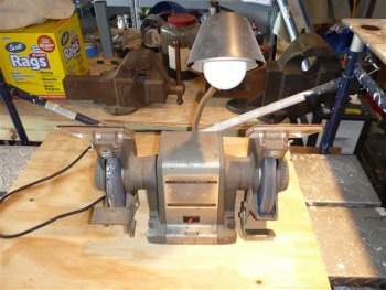
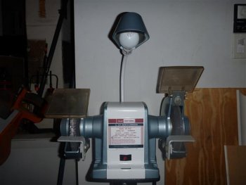
Craftsman Bench Grinders with one of the following model prefix's : 397, 257 or 115. Affectionately known as Block Grinders, they were overbuilt back in the day and all of them have a very unusual look, very 'blocky'. Below are 2 pictures of the 'before' restoration phase of each style of body they have.
This is the earlier version, slightly rounded top and metal eye shields. This is one I restored for my father last Christmas.
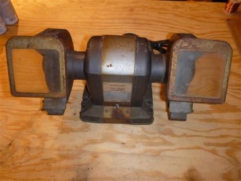
This is slightly newer (late 60's in to the 70's), square body and plastic eye shields. Lamps can be on either version. This is a 3/4 HP and the one I'm explaining in this thread.
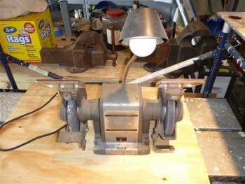
Why are these so good? Simple answer...they were OVERBUILT to a huge degree, simple components and practically impossible to break. The housing of these is a cast metal and can break, but the motor inside will still run. Capacitors on some later models are still available today from various sources and the bearings used (even different sizes depending on HP) are common so even getting parts is not hard. Once I restored mine, I compared the power to my friends 1.5HP Baldor buffer (which is about 4-5 years old at this point). I can physically stop his Baldor buffer with a 1 inch piece of steel tube just leaning in to the wheel. My craftsman? I can NOT stop. I don't have enough oomph, I can slow it, but it has enough torque to STILL turn.
Here is my 3/4 HP I picked up off Craigslist with the stand for $40. I drove an hour each way to get it, but it was well worth it. Value depends on HP, and 3/4 and up are rather rare.
Here is the full thing, on the stand as I picked it up.
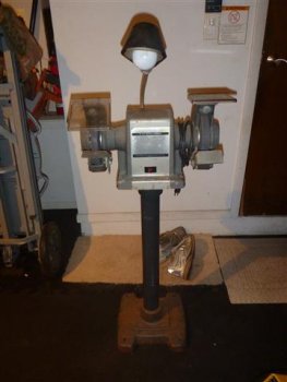
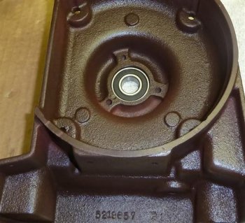
Front shot once I removed it from the stand. When I tested this, I noticed it seemed to stop almost as if there was something braking the spindle when the power was cut. Usually these will run for a while and slow down naturally (45 - 120 seconds if not more). This tipped me off that a bearing was probably bad which necessitated the restore.

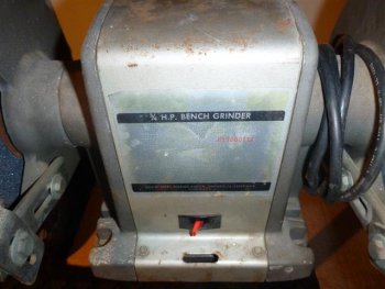
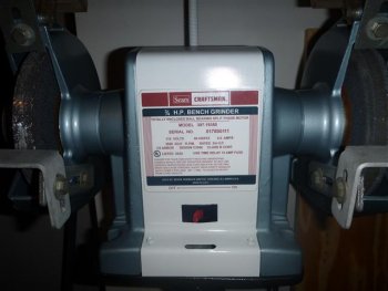
Close up of the label, as time had taken its toll. When I restore a piece of equipment, I do my best to restore all of it. You'll see what I had to do for this later.
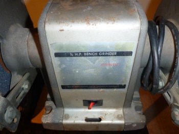
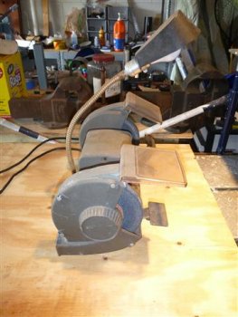
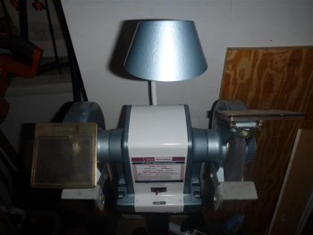
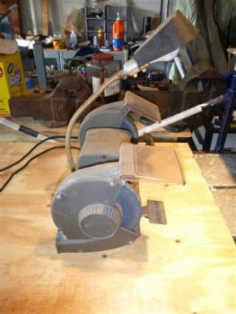
Side view showing the lamp and the eye shields a bit better.
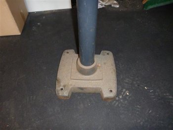
Base of the stand....a little rusty isn't it? Rust like this usually lets me know I need to check other places and dismantle the tool to be sure of the innards!
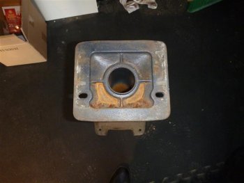
This is the top of the stand, where the grinder was bolted down. Rust in here was rather odd and most folks would have just used the grinder as is, but with the base being rusted, I knew to break it all down to be take care of any issues. Plus once the rust is removed and painted, it could last another 50 years.
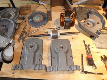
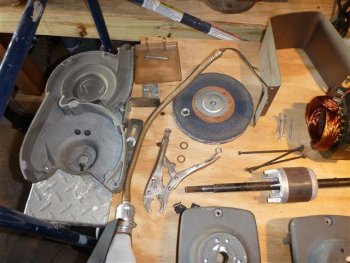
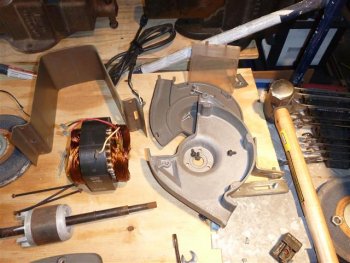
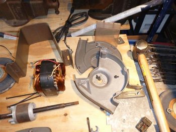
Now comes the fun part...tearing it all apart!!! The drill press restore I did was far more complicated than this, trust me, anyone thinking of making knives can disassemble this in their sleep!
I have read a lot of advice about what equipment is needed and or, what brands are best for a certain piece of equipment. The issue is that LOTS of times, the best is subjective and yet it usually leads to expensive options. One that practically unanimous is for buffers. Baldor buffers are quality machines and I've always thought so. My problem though is that I've needed one (not just for knife related work) but have not had the $400 - 600 in my wallet that is their price tag. Since lots of us just starting out don't have those funds, or perhaps you have one but need a second, or even those who need a replacement tool for one that you can't repair, I decided I should post this up as what I view as a great alternative (if not slightly better!).
I love the older/vintage tools. I believe they are made better than MOST of today's tools. There are some which are better than others. Baldor buffers even on Craigslist are usually pricey, but I have an alternative most people overlook.
Craftsman Bench Grinders with one of the following model prefix's : 397, 257 or 115. Affectionately known as Block Grinders, they were overbuilt back in the day and all of them have a very unusual look, very 'blocky'. Below are 2 pictures of the 'before' restoration phase of each style of body they have.
This is the earlier version, slightly rounded top and metal eye shields. This is one I restored for my father last Christmas.

This is slightly newer (late 60's in to the 70's), square body and plastic eye shields. Lamps can be on either version. This is a 3/4 HP and the one I'm explaining in this thread.

Why are these so good? Simple answer...they were OVERBUILT to a huge degree, simple components and practically impossible to break. The housing of these is a cast metal and can break, but the motor inside will still run. Capacitors on some later models are still available today from various sources and the bearings used (even different sizes depending on HP) are common so even getting parts is not hard. Once I restored mine, I compared the power to my friends 1.5HP Baldor buffer (which is about 4-5 years old at this point). I can physically stop his Baldor buffer with a 1 inch piece of steel tube just leaning in to the wheel. My craftsman? I can NOT stop. I don't have enough oomph, I can slow it, but it has enough torque to STILL turn.
Here is my 3/4 HP I picked up off Craigslist with the stand for $40. I drove an hour each way to get it, but it was well worth it. Value depends on HP, and 3/4 and up are rather rare.
Here is the full thing, on the stand as I picked it up.

Front shot once I removed it from the stand. When I tested this, I noticed it seemed to stop almost as if there was something braking the spindle when the power was cut. Usually these will run for a while and slow down naturally (45 - 120 seconds if not more). This tipped me off that a bearing was probably bad which necessitated the restore.

Close up of the label, as time had taken its toll. When I restore a piece of equipment, I do my best to restore all of it. You'll see what I had to do for this later.

Side view showing the lamp and the eye shields a bit better.

Base of the stand....a little rusty isn't it? Rust like this usually lets me know I need to check other places and dismantle the tool to be sure of the innards!

This is the top of the stand, where the grinder was bolted down. Rust in here was rather odd and most folks would have just used the grinder as is, but with the base being rusted, I knew to break it all down to be take care of any issues. Plus once the rust is removed and painted, it could last another 50 years.

Now comes the fun part...tearing it all apart!!! The drill press restore I did was far more complicated than this, trust me, anyone thinking of making knives can disassemble this in their sleep!
Last edited:


