No Weld Grinder WIP

teter09

Well-Known Member
I originally wasn't going to post this, just because I wasn't sure if it would be allowed since the plans aren't mine. Then I figured if I just skipped measurements I should be ok!

I will walk through this as I did, but ignoring some of the boring parts. Such as measuring and drilling all the holes in the different pieces. Boring (and also guarded by the Boss!)
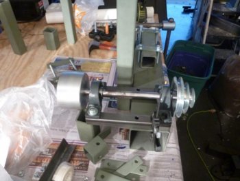
Once I did that, I primed all the tube stock and straps as well as the tracking/tension block. Once dry, I did a rough assembly. One thing I noticed was that I didn't like all the bounce in the drive wheel with the pillow blocks so close together on the base tube. I opted to modify this by using 1" x 1" square tubing mounted to the base tube which would allow one pillow block to be mounted over the left side of the base tube and the other to be set a full 4 inches to the right of the base tube, this eliminated a lot of wobble from the drive wheel.

This picture shows my adaptation from the side as I was working to mark my holes in the base tube, pre drilling.
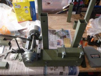
Small P1030354.jpg


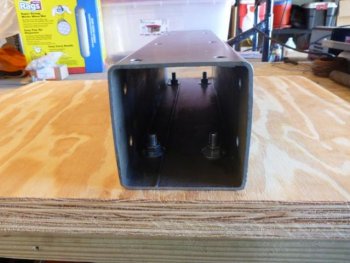
This picture shows it from the back of the grinder, as I was marking holes to drill.
Small P1030355.jpg

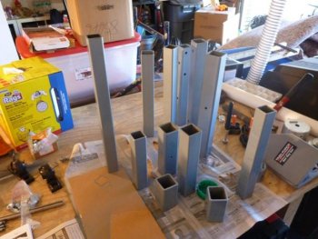
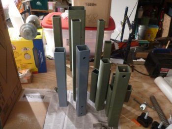
This shows the tubes which are primed (Green) with those I'm painting to final color (blue). I really like this blue, I have a case as its discontinued and you'll see my vise later on matches!
Small P1030356.jpg

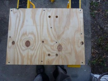
I felt the recommended size base was too large, so I scaled it down. I did stack the 2 pieces of 3/4 plywood, I marked and drilled the holes so that the washer and bolt head wouldn't stick out of the bottom board. This pictures shows the holes drilled and they are screwed together.
Small P1030475.jpg

All painted!
Small P1030474.jpg

Base tube mounted
Small P1030477.jpg

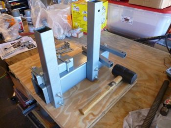
Tool rest holder mounted, verticals mounted. I started to add the pillow block tubes, but removed them after this as I didn't want them dinged too much when I tried adding the tool arm holding tube.
Small P1030479.jpg

Added the tool arm holder as well as the tension arm and the tracking block.
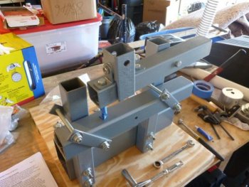
Small P1030480.jpg

I decided early on to order one of the rotating arms that was sold by Usaknifemaker (the design is in the plans). Except they no longer carry it. When I inquired about it, they said I should contact a certain waterjet company who had previously been highly recommended on here. After 6 emails and 4 phone calls (including messages) being left unreturned, I decided not to waste anymore time and I've told others not to waste their money there either! But I also decided to build my own. Here is the picture of it next to the template. I think it came out well, and didn't cost 1/4 of what I would have probably been willing to pay originally!
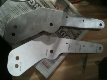
Small Rotating Wheel Arm.jpg

I had read about moving the spring from behind the tension arm, to under it and resting on the tool arm tube. I liked what I'd heard so I did make this modification. I'll add more pictures and explanations tomorrow.
 
I've finally gotten time to post the continuation for this....

I had a tracking problem I posted about here under Shop Talk. Essentially after doing a shop visit with Josh not long ago, I saw his KMG operate in both forward and reverse, so I decided to test mine by cranking it around by hand in both directions. Forward worked fine, but reverse caused the belt to track right off the wheels! Not good! So I got some advice from members here and then went back to it. I'll post my resolution here since it is relevant, but not the whole thread.

My dad came through town on his way back from working in North Carolina (he is a general contractor) and stopped in. He has one of the really nice self leveling multi direction laser levels. It allowed me to verify my base tube was level, and my vertical arms were directly 90 degrees from the tube. I was then able to verify my tool arm and my swivel arm where perfectly aligned as well.

When I checked my drive wheel, while it was plumb to the contact wheels axis, the center line was about 1/4 inch off. Meaning the center of my drive wheel as you trace the wheels like the belt rotates was off to the right. I fixed that and then moved on to the tracking wheel.

I discovered a few things here. I built two tension arms since I wasn't sure how I wanted my spring, in the back like the NWG plans or in front like a KMG (suggestion I had read). When I had tried the spring in the rear, I felt I couldn't get enough tension, even with two springs as suggested. I tried a compression spring which I had purchased to give me more tension but locate the arm in about the same spot as the door spring when attached at the rear. When comparing these while hand turning the belt backwards, I realized something. The higher the tracking wheel, the more off of plumb it's adjustments get!!!

With this I changed a few things. I found too much play in the tension arm. When a belt was mounted and i was adjusting the tracking i could see the arm moving from left to right. It turned out that the 3/8" bolt was bending. I drilled out the holes to accept a 1/2 inch bolt and also got one which only had the last inch threaded, so the threads couldn't have any play. I kept the spring in front. I also chopped it in half so that the arm is practically parallel to the tooling arm, but it is a stout spring so it adds more tension than there was with the spring in the back. Finally I aligned the center with the centers of the contact wheels and drive wheel.

After all this.... It now tracks forwards and in reverse!! Though reverse doesn't stay on the wheels 100% aligned, but I feel it is close enough for now and I think I am set up pretty well with it for now!!

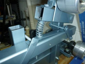
Here are pics of the spring assembly. I fabricated a small piece of 1/8" metal by heating one end to bend it at a 90 degree angle to lock it under the clamps in the rear, while the front was locked in by the clamps on the front. I drilled a hold to accept a cut off 3/8 x 1.5" bolt to retain the spring.
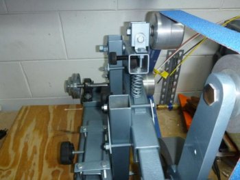
Here is the front view of the assembly
Small Spring Front View.jpg

Here is a side view of the spring assembly
Small Spring Side View.jpg

I really like having the spring here. By changing the tension arm's bolt from 3/8 to 1/2 and using the spring in the front, it really tracks better than having the spring in the rear. The spring in the rear, even doubled up as I'd read somewhere, just didn't seem to keep consistent pressure on the belt.


Once I had figured out the tracking, the next week my VFD came in. My shop visit with Josh had inspired the copy cat in me. He had his system set up with a single VFD, but it was wired with the outgoing connections as a plug. Why? He has multiple motors that are 3 phase (not the least of which is that awesome hydraulic surface grinder he has a WIP on for the restoration) so he can use 1 VFD for all those motors! Since I'm just starting out, I wanted the option of being able to pick up more 3 phase motors and using them without buying another expensive VFD!

As I researched enclosures for the VFD though, I came across a worry some issue. I'd read on some tool threads I frequent, that someone had a shop fire due to a VFD overheating. They used a wooden enclosure that worked well enough, but wasn't allowed by code. What does that mean? No possible insurance claim! Ouch. I decided I could save myself some money by doing the wooden enclosure, but it wasn't worth the risk, so I got a decent price on a Nema 4 enclosure and went to work wiring it up!

First thing is the back of the enclosure has a 1/16 sheet of aluminum as a heat sink. I deliberately purchased an oversized box since I wasn't planning on using fans to start. I have one if I need it, but I'd rather not open the box up anymore than I have to. So how do you make all these openings in what should essentially be an airtight enclosure without nullifying its rating? Use watertight seals of course! They sell them at Home depot. I was able to match my cord that plugs in to my 240V outlet to a 3/4 inch watertight fitting. It was REALLY rough, so tight I was having to gently heat the rubber on the wire so that I could fit it around the outside of the fitting, but I did it! Just to be sure it wasn't letting anything in, I wrapped it up with electrical tape really well, though it wasn't really necessary. When I let the rubber cool, I couldn't actually pull the fitting back off the cable!

Next up the plug. For this I used a plastic enclosure, very carefully measured the outline and cut the whole. I then sealed the edges of the box by using a silicone caulk that an electrician friend uses on his jobs. I also used gaskets around the outlet plug itself to be sure nothing could get in.

Next is the Forward/Reverse switch and speed control. I again used a kit of watertight electrical supplies. It basically is a 3/4 inch tube with watertight fittings (one straight and 1 90 degree elbow). I ran my wire down through it (wow what a pain) and connected it. I had picked up a control box that is like the radio shack hobby boxes from a place called Skycraft as well as my switch and potentiometer.

I used a hunting trick for testing if there was air escaping or incoming anywhere. I have cornstarch in a small bottle, and puffed it all around the enclosure when the VFD was operating. I did it all around the wires and plug that were in the box to see if any air was moving. The stuff didn't move at all. I even directed it at the fittings and checked inside with duct tape (seeing if the white specs would stick to the tape)....NADA!!!

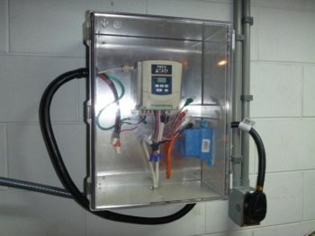
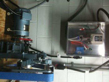
Quick view of the front of the VFD enclosure. Left side is the power cable that plugs in to my wall outlet. Bottom is where the FWD/STOP/REV control and Speed control extend out to the control box. Right side where you see the blue is the plug.
Small Front VFD.jpg


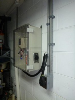
Right side view of the VFD, showing the plug for any 3 phase motors I might have.
Small Side VFD.jpg

Another huge advantage of this for me is I LOVE restoring old machines. The old ones just work better, are simpler and last longer than current ones. I have a lame Ryobi drill press for use now until I finish the restoration of my 1952 Rockwell. I've restored my 1964 Craftsman Grinder and also have a mid 50's Band saw I will be starting shortly. Most people don't charge as much for a 3 phase motor since most people can't use them. Now I can!

Once I mount my motor I will update this with more pictures!
 
Today was a very productive day in my garage today. I managed to finish the restorations on a few bench vises, throw out some old stuff I no longer needed, finally mounted my anvil and got a bit closer on my NWG!

I do apologize ahead of time....my girlfriend went to California yesterday for a mini vacation and borrowed my camera. Which means you guys get stuck with my crappy Iphone 3GS camera!!

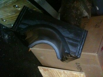
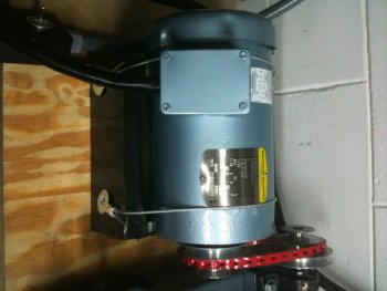
My Baldor motor is 2HP. Unfortunately it has no mounting bracket at all, since it was designed for a marine application. I had to fabricate a cradle where the motor will sit inside and I will use some vinyl coated wire in order to tie it in to the cradle. Here is a pic with it on the horn of my anvil drying. You can see the semi-circle that is cut out so the motor will sit in it and not be able to wobble.


Painting Motor Mount.jpg

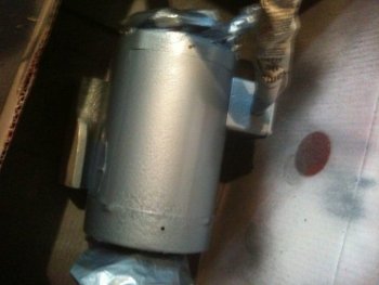
My motor is a green color. It isn't a bad color, but doesn't match my grinder, so I decided to tape all the important parts off and paint it. Here is a shot of it in my make shift painters booth (cardboard box).

Painting Motor.jpg

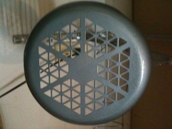
Just the fan end cap that I pulled off and painted to match the grinder frame.

Painting Fan Cage.jpg

I'm assuming another layer of paint tomorrow and then I'll be ready to mount it to the grinder base and rock and roll! Kind of scary that I'm almost there!
 
Well, it is finally DONE!!!!!

I guess there really isn't too much more to report here. I used 1/8" Vinyl coated aircraft cable to mount the motor in to the cradle. It doesn't move a lick! I mounted the cradle to the grinder base using 3 inch Torx Deck screws, just something I had around the house.

Here is the motor all mounted and hooked up using the V-belt. As you can see the motor now matches the grinder frame, which just makes it look better in my opinion. I know it will get dirty and scratched later on, which I don't care about. Something about a new build or restoration though, I have to see it through and make it look good to START, regardless of how it will be used and abused!
Small Mounted Motor on Grinder Base.jpg


Overall view of the grinder at its probable home on the bench on my wall, right under the VFD.
Small Complete Grinder.jpg

And....drumroll please......Here is the video of the first time I threw the switch!
[video=youtube_share;2VWNriLGxUI]http://youtu.be/2VWNriLGxUI[/video]

The video makes it seem a lot louder than it really is. Once I took this, I called up my dad to start it up for him, even on speaker phone he couldn't here it running. I'm thinking that is a good thing, hopefully neighbors won't be able to hear it if I decide to work late some nights.

Questions or thoughts? Hopefully this will help someone in the future when they decide to build their own.
 
Beautiful job on your grinder and the VFD install !!!!

LOVE that you wired a plug to the VFD's power supply line also. I should've done mine like that so I could run my MIG in the front of the shop also. As it stands I've gotta plug the mig in behind the Evenheat.

Hmmmmm You've got me thinking now.

With you're attension to detail you'll be churning out beautiful knives in no time at all.

Bravo :35:

-Josh
 
Back
Top