WIP Grinder build

Brad Lilly

Moderator and Awards Boss
I posted some grinder questions on here a while back and Chris Williams of Wilmot grinder's gave me a lot of valuable advice. He also got me to contact Terry the Canadian who came up with the original idea. Terry is a great guy and gave me a bunch of advice and encouraged me to try to build a grinder. The plans are for the EEFR grinder are on the Wilmot site and in Cad format. I was lucky enough to find company who could read the Cad format into their water jet and cut out the parts. So here we go
IMG_0698.jpg

The biggest job is drilling holes, lots of holes. Since the grinder is made from 1/2" plate drilling would be a nightmare without a drill press or mill. I have been carefully laying out the holes and punching the centers, then off to the drill
IMG_0704.jpg

More to follow, this is a winter project for me so it is going to be a bit slow.
 
I had a little time this weekend to do some work on my grinder. There is not a lot of tapping to do on this build but there is some. I drilled and taped one side of the idle wheel arm then bolted the hinge on and drilled the other side. I also drilled right through the arm so when I taped it the chips could fall out .I live by the KISS principal.
IMG_0705.jpg


This is where I’m at right now.
IMG_0710.jpg

IMG_0713.jpg

The water jet cutting is a little rough but I'm building a grinder not a piano.:) I still have to gear up a pivot for the idler arm and pick up some 1 ½” square stock. I also have to drill and tap the four bottom bolts that hold the bottom plate on.
 
Brad, I built the same grinder a while ago... Ed Caffrey gave me the best tip one could receive when dealing with this set up. He told me leave the rear spring out, move the tracking/ tension arm forward and add a front compression spring rather than a rear tension spring and it has made all the difference. Tracking went from so-so to KMG accurate with this small tweak.

DSC_0010.jpgDSC_0009.jpgDSC_0007.jpgDSC_0006.jpg
 
Last edited:
I used the largest spring they had at the hardware store... not too exact huh? hahahah. Anyway, I did buy a spare so I'll dig it up and tell you the size. If you guys have an Ace Hardware up in CA, they carry a varied supply of them.
 
Great tip. I should try that on my NWGS.

You'll love it if you do. Changing belts is so much easier and you don't lose tension or have to spend time with continuous tracking adjustments. My mantra has always been, "Only a poor craftsman blames his tools," but truth be told, better tools sometimes take you from sub-par or par to phenomenal... at least by comparison of ones old work. :)
 
Great project you've got going here. I'll be following it with interest as I'm in the process of same type project. I got the platen wheels and tracking wheel turned yesterday with bearings installed. I do have a question here, how does having the tension spring as a front mounted compression rather than a rear mounted extension spring make a difference in tracking?

I sorta liked the looks of the extension spring at the back end, BUT - if there is any real difference then I can surely use a compression spring. I know nothing about 2"X72" grinders, never even seen one. So, I'm looking for info and guidance.

Thanks to all for any suggestions and guidance,

Ken H>
 
There are a few factors at work in this but what I noticed is that the rear spring did not keep consistent tension on the belt. I tried using a larger rear spring, then two then I gave up and took Ed's advice and now one single spring keeps the proper tension on my belts. Every time the tension changed, the belt moved up on its axis which forced an adjustment on the tracking. Having the "Ed" version allows for no movement and this ends keeping your tracking true. It also makes it easier to change belts. Let me dig up the post where it was explained to me.
 
Here you are...

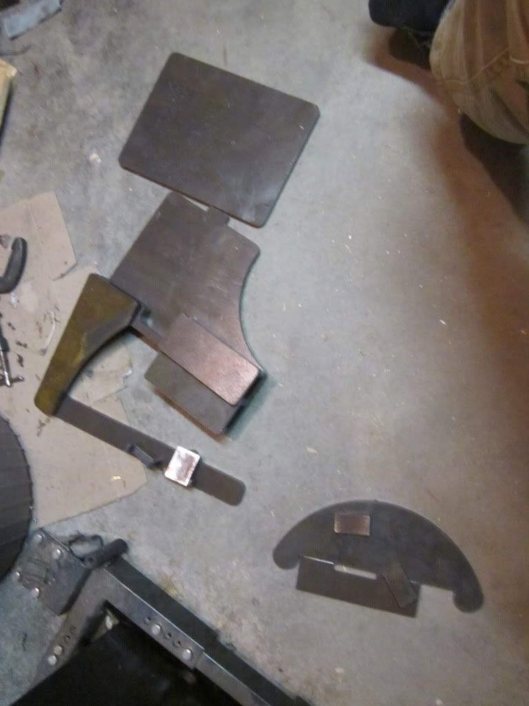
At Paul's request, here is some more....I just finished building one for Jim Clow (Boatbuilder). The more I play around with these grinders, the more I like them. I might have mentioned some of these thing in my previous post, but I think they are worth repeating and keeping all in one place.

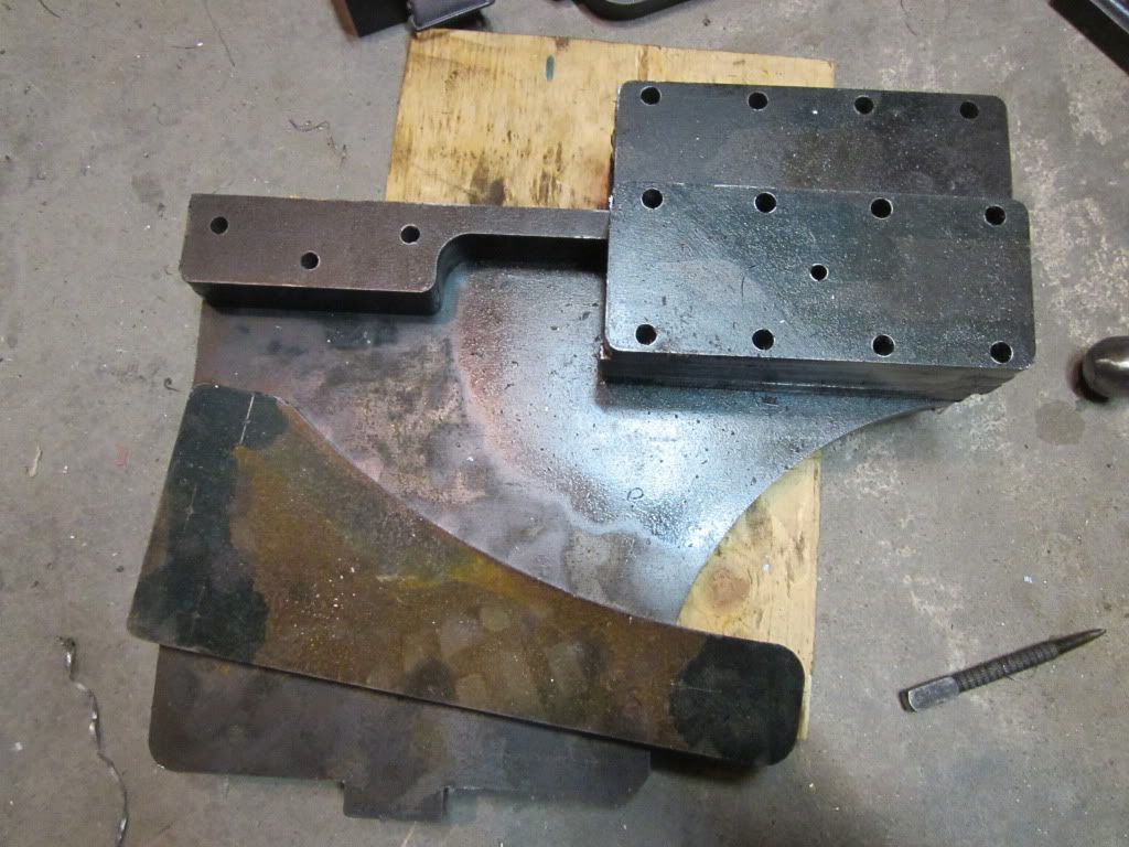
The first and foremost modification that I think is a MUST on these grinders is to dump the tension spring for belt tension...it just works poorly, no matter what you do. A compression spring is the only way to go IMO. It's done by mounting the idler arm, then locating where to drill/tap a 3/8"-16 threaded hole. Using a piece of all thread with a nut to tighten it down (make sure it doesn't protrude inside the receiver). The spring seat was made on my lathe from a piece of 1" round cold rolled. The hardest part is tapping that thing all the way through. :) The spring came from the local Ace Hardware store. I suppose a person could build two of the spring seats, and mount one to the bottom of the idler arm, but I've not found the need....and it's just more parts to build.

GIBcompressionspring2-1.jpg


GIBcompressionspring1-1.jpg


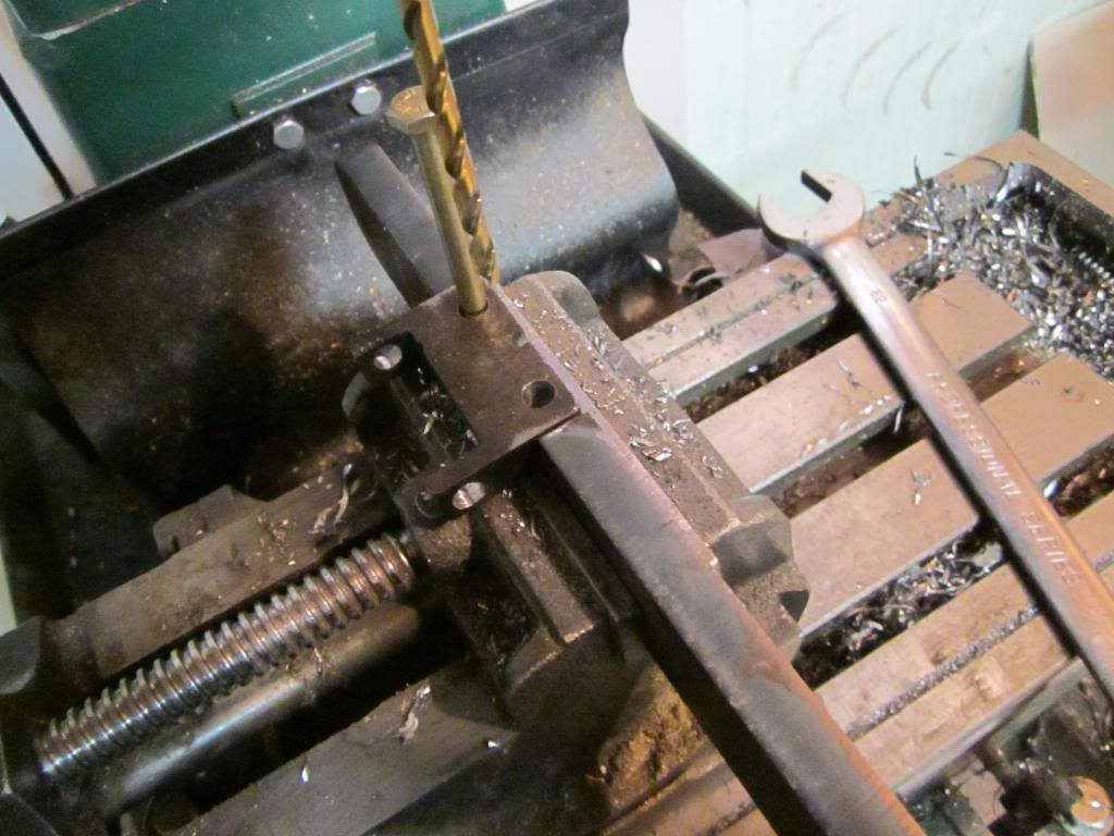
Next, do not use the mounting hole for the idler arm. Drill another 1/2" hole as close to the end of the idler arm as is practical. This allows the idler wheel to be moved further forward, making for more precise tracking, and also lengthens the "throw" for more leverage when changing belts.

GIBidlerarmpivot-1.jpg


Idler wheel mounting....Most are using a simple 1/2" nut for the spacer between the idler wheel and the mounting block. I surface ground the nut down to 5/16" thickness, and that will bring the wheels into alignment (very important for smooth running and tracking).

GIBidlerspacer.jpg


I also like setting up the tracking adjustment like this:

GIBtracking.jpg


Mounting the drive wheel.......when putting the drive wheel on the motor shaft, put it on just far enough to get a good bite with the set screw. Because the motor is mounted on inside of the frame, this makes the shaft too short if you mount the drive wheel all the way on the shaft. (no pic of that one)

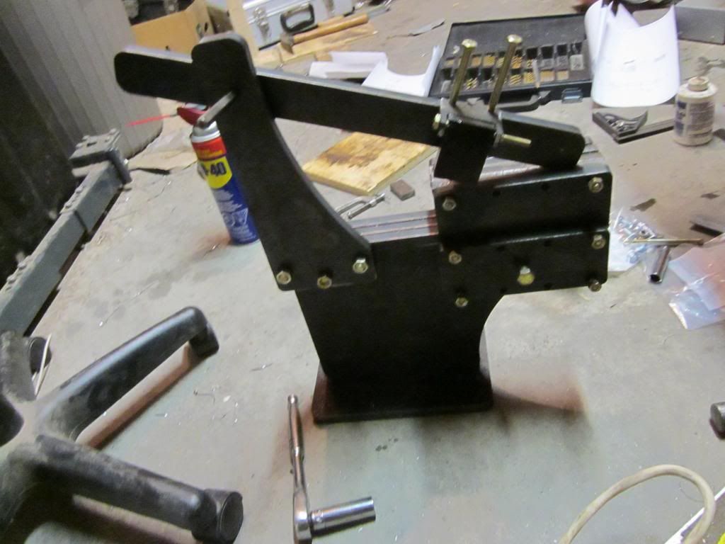
If your going to mount the auxiliary receiver for a work rest such as the MAPP arm. Mount those parts one bolt hole forward....otherwise you must have an extremely long tooling arm for it to work.

GIBAuxreceiver-1.jpg

(that's my 10" wheel/tooling arm....I had to test Jim's grinder to make sure everything was working right......I'll be modifying my grinder by moving the aux receiver one bolt hole forward as time allows)

Finally, on the inside of the KBAC-27 controller....there is a jumper (J4). From the factory it is set to 1X (motor speed). If you have a 1725/1750rpm motor, I would recommend setting that jumper to the X2 position. I found that at 1X the grinder is too slow to efficiently grind with heavy grits.

That's it for now....but I'm sure if I put more of these grinders together, I'll be tweaking as I go.
 
Thanks for the info - that gives a "reason" for it working. I do so much better when I can understand the reason behind an ideal.

Those photos have some good detail and will be very useful.

Ken H>
 
Thank you Brad, but credit goes to Mr. Caffrey as he is the one that inspired my modification of his modification... if that makes sense. Either way though, if you try the rear spring and then this mod, you will never go back! I almost gave up on my GIB and opted for a Bader but after it was modded, it has earned a place in my shop as it run like one of the big-boy-grinders.
 
Brad,

Did you finish the grinder? Are you happy with it? Why did you start with the CAD files and having the pieces water jetted rather than use Polar Bear Forge's GIB frame kit? I sound like my kids, enough questions already.

Jay
 
Back
Top